If you want to race distortion figures, use the ef but followed with cfp vas. The cfp is awesome with a fet.
You should be able to match OS s apt design in performance. 😉
You should be able to match OS s apt design in performance. 😉
danielwritesbac said:
Of course both amplifiers should do well, but the interesting part (for me) is when there's a difference and then spotting the cause of it.
They sound divine Dan. The biggest change anyone can do to improve their audio clarity and sound scape is to actively drive their speakers. There are 6 of these, driving two 3-way speakers through a digital crossover.
Also, these are very accurate amps. They are not giving something that is not there.
homemodder said:If you want to race distortion figures, use the ef but followed with cfp vas. The cfp is awesome with a fet.
You should be able to match OS s apt design in performance. 😉
Hi Homemodder,
I'm not chasing THD anymore. I have this design low enough that any improvements in that regard will never be detected.
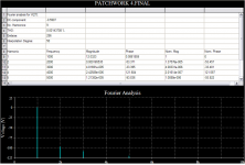
FFT 1k, 9 harmonics:
EDIT: Oops! Wrong chart.
Attachments
MJL21193 said:They sound divine Dan.
. . .
Also, these are very accurate amps. They are not giving something that is not there.
. . .
I didn't mean any disrespect. What I meant was. . .
Simply put, there's two of them, they're both great; so, which one is more fun? 😀
danielwritesbac said:
I didn't mean any disrespect. What I meant was. . .
Simply put, there's two of them, they're both great; so, which one is more fun? 😀
No disrespect taken Dan. 🙂
I seriously don't think there will be a discernible difference between the two during normal operation. They are basically the same, utilizing the same "tricks".
Fun? Well...cheer up my friend, you need to be in a good mood to have fun! Maintaining a blissful attitude will greatly improve the listening experience. 🙂
Thank you! 😀
I was trying to say that your ears will do a different sort of "detection" than measuring equipment. And, I was trying to correlate that to Mr. Nelson Pass's statement about amplifiers being within the scope of the entertainment industry. So, like, when all of the options are good, that's the time to choose the most pleasant among them.
At about that point, I had confused myself. lol!
P.S.
In making the comparisons between such similar amplifiers, it would be great if your NFB cap is exactly the same model on both amplifiers. You know, repeatable results and all that. 😉
MJL21193 said:
Hi OS,
No, he was referring to the current mirror - that's clear.
My PSRR is excellent for this amp and I have no intention of replacing my simple single resistor with a "proper" CCS.
🙂
I was actually referring to this. What makes the base voltage constant to generate a constant current? A capacitor at the base of U2 would even make it "more constant".
I see a 2 volt p-p signal injected into your power supply for ripple effect.
The ripple on a real power supply depending on the number of capacitors and the current drawn could be much more than this.
I would be inclined to model the actual PSU with a signal applied to the amp running at full bore.
Simulators assume a power source with zero impedance.
Attachments
Nico realises this is not an effective current mirror.Nico Ras said:A final remark, I am not sure if your CCS is really up to task, it will vary with varying supply voltage, the diode is referenced to a resistor that will drop voltage depending on the supply.
I would remove the 470 Ohm resistor and use another diode or maybe two diodes.
I could interpenetrate it wrong and you intended something else with this circuit.
Nico
AndrewT said:Nico realises this is not an effective current mirror.
Your explanation was brilliant!:
"[It is]. . . an active load driven in anti-phase to the current. . . The effect is similar to a mirror. But, I would never call that a mirror. The characteristics of the diode and transistor are probably too different to be well matched and [it is an added complication]. . . to try to get a match at the operating current." (quote is from a different thread)
Oh my gosh! Good point! This relates to a post that I made, thinking it was simple, but it wasn't. It will be necessary to have approximately similar DC offset for both amplifiers before an ear comparison can be made. Any change in the current/voltage at the NFB cap will make an obvious difference to the ear--perhaps not accurately highlighting the differences in the circuits themselves.
So, I take it that there's an extra bit of bother for adjusting, before this amplifier can be compared with its siblings.
Okay, sure. But that's not the question.
The question is, what benefit do you receive in trade for the extra bother?
I'd expect that current mirror to make currents in the LTP unbalanced, increasing distortion and DC offset. (Tail current splitting is determined by it as the next stage draws very little current)
Nico Ras said:
I was actually referring to this. What makes the base voltage constant to generate a constant current? A capacitor at the base of U2 would even make it "more constant".
AndrewT said:Nico realises this is not an effective current mirror.
Hello Nico and Andrew,
I hope you had some good times over Christmas. 🙂
It is, other than the mismatch in resistor value, the same as the 2 transistor version. The transistor that the diode replaces is tied base to collector and is acting as a diode itself. It performs in the same way as the diode connected transistor - constant voltage to the base of the first transistor, regulated by current draw.
True, a matched transistor would seem to be a better choice, but it's not needed, as the legs are not equal anyway. This seems to be the key for the better results at high output - a full .003% drop in THD at high output. Even better at higher frequency where the improvement shows to be as much as .01%
megajocke said:I'd expect that current mirror to make currents in the LTP unbalanced, increasing distortion and DC offset. (Tail current splitting is determined by it as the next stage draws very little current)
Hi Mega,
It seems to do neither in my simulation. I will see if I have time later to put it to the test, although the THD measurements are beyond me right now (I'm working on procuring a distortion meter) I could certainly check offset.
How does the current divide and what is the C to E voltage of the current mirror? It could be out of headroom and saturated when the buffer was removed.
megajocke said:How does the current divide and what is the C to E voltage of the current mirror? It could be out of headroom and saturated when the buffer was removed.
A better question is why would this imbalance in the legs of the LTP have a negative effect of PSRR? In the chart shown earlier, the results were good, but this was taken before this mod. I thought, incorrectly I now see, that the result would be unchanged. In fact, PSR has risen to -10db at low frequency and the mismatch is the cause. Why?
I guess the answer will not effect the outcome - I'll need to undo this mod and return the mirror to it's original state.
MJL21193 said:A better question is why would this imbalance in the legs of the LTP have a negative effect of PSRR?
I'm not sure, but you might try making some temporary models in the sim for the transistors in the input diff pair (Q5, Q6, U4, U5, U2). Make these the exact same as the existing models except delete VAF and VAR. The simulator will set them to their default value of infinity (totally flat output curves). Use these models only in these specific places, not anywhere else in the sim. Then re-run the PSRR. If it gets good again, you'll know it's an Early effect thing. You could then narrow it down further by using these infinite Early voltage models for only Q5 and Q6, only U4 and U5, or only U2.
The Early effect changes Ic when Vcb changes. When the mirror has a scale factor that's equal to 1, any shift in the Ic values that occurs simultaneously is (mostly) canceled out in the mirror output. That is, if I1-I2=0, then K*(I1-I2) is also zero. Here the K is meant to stand in for the common-mode change in Ic due to Early effect. But when the mirror gain is not 1, that cancellation does not occur, and the common-mode current change is converted to a difference-mode current at the mirror output. At least, that's what I think is going on 🙂.
Another way of looking at this in the simulator would be to probe the current at the mirror output when you vary the AC component of the supply.
Hi Andy,
I tried this but it didn't make a difference - still showing terrible PSR down low.
It's the same result for the diode configuration as the standard Widlar mirror with the resistors mismatched.
Before someone blames my resistor current source, here is the PSRR with the balanced LTP:
I tried this but it didn't make a difference - still showing terrible PSR down low.
It's the same result for the diode configuration as the standard Widlar mirror with the resistors mismatched.
Before someone blames my resistor current source, here is the PSRR with the balanced LTP:
Attachments


When I change to an active CCS on the LTP from the resistor source, this improves the result, but still not close to where it is with a balanced LTP.
The decrease in THD at higher output levels is baffling too. Why would it do this in the first place? I wouldn't bother if the change was unremarkabe.
The decrease in THD at higher output levels is baffling too. Why would it do this in the first place? I wouldn't bother if the change was unremarkabe.
Hi John,
From your harmonic analysis graphs the offset is almost > ½V.
I took a few moments and captured your diagram into microcap. I see the same off-set and cannot cure it unless I make significant component changes.
The current mirror does not do its job since the legs if the LPT is 3.5 mA and 1.3 mA.
THD I get much higher numbers at the same 12V output. It is 0.17% at both 1 and 10 kHz @27 degrees centigrade and 0.6% @ 50 degrees centigrade.
There seems to be a thermal problems too. Current increases with temperature. Bigger problem is that it increases more in the NPN side.
My models may be very different from yours though.
I will play more later and report back.
Kind regards
Nico
Hi Nico,
Models used:
.model 2sa970 PNP(Is=465.4f Xti=3 Eg=1.11 Vaf=57 Bf=407.6 Ise=4.683p Ne=2.051
+ Ikf=.3998 Nk=1.192 Xtb=1.5 Var=100 Br=1 Isc=465.4f Nc=1.048
+ Ikr=6.032 Rc=2.343 Cjc=11.59p Mjc=.4014 Vjc=1.155 Fc=.5 Cje=5p
+ Mje=.3333 Vje=.75 Tr=10n Tf=1.252n Itf=1 Xtf=0 Vtf=10)
.model 2sc2240 NPN Is=99.13f Xti=3 Eg=1.11 Vaf=422.2 Bf=352.8 Ise=1.179p
+ Ne=1.782 Ikf=.4704 Nk=.9631 Xtb=1.5 Var=100 Br=1.663 Isc=555.1p
+ Nc=1.796 Ikr=5.85 Rc=.2032 Cjc=7.561p Mjc=.2472 Vjc=.3905 Fc=.5
+ Cje=5p Mje=.3333 Vje=.75 Tr=10n Tf=1.295n Itf=1 Xtf=0 Vtf=10
.MODEL MPSA18 NPN(Is=33.58f Xti=3 Eg=1.11 Vaf=100 Bf=2.365K Ne=1.579
+ Ise=166.7f Ikf=.1172 Xtb=1.5 Br=5.774 Nc=2 Isc=0 Ikr=0 Rc=1
+ Cjc=4.948p Mjc=.4109 Vjc=.75 Fc=.5 Cje=7.547p Mje=.3765 Vje=.75
+ Tr=800.3p Tf=310.1p Itf=.6 Vtf=6 Xtf=35 Rb=10)
.MODEL 2SA1381 pnp
+IS=5.5544e-14 BF=148 NF=1 VAF=580
+IKF=0.2163 ISE=2.0546e-15 NE=1.5 BR=1.892
+NR=1 VAR=100 IKR=0.187544 ISC=2.04807e-09
+NC=1.5 RB=10.18 IRB=2.0e-6 RBM=0.02
+RE=0.62 RC=3.572 XTB=0.907 XTI=3
+EG=1.206 CJE=9.572e-12 VJE=0.748 MJE=0.371
+TF=8.0312e-10 XTF=1 VTF=10 ITF=0.01
+CJC=1.147e-11 VJC=0.541 MJC=0.329 XCJC=0.9
+FC=0.5 CJS=0 VJS=0.75 MJS=0.5
+TR=1e-07 PTF=0 KF=0 AF=1
.MODEL MJE15030 npn
+IS=3.894e-11 BF=312.524 NF=1.0979 VAF=9.9963
+IKF=0.796201 ISE=2.37397e-09 NE=1.94897 BR=0.14246
+NR=1.64791 VAR=99.9749 IKR=0.00539895 ISC=2.33175e-09
+NC=2.79024 RB=267.202 IRB=9.99994e-13 RBM=0.299835
+RE=3.04316e-05 RC=0.252928 XTB=0.1 XTI=3.92812
+EG=1.05 CJE=2.42998e-09 VJE=0.794171 MJE=0.569313
+TF=1.87986e-09 XTF=1000 VTF=1835.34 ITF=270.188
+CJC=2.43127e-10 VJC=0.4 MJC=0.361453 XCJC=0.802892
+FC=0.8 CJS=0 VJS=0.75 MJS=0.5
+TR=9.86194e-06 PTF=0 KF=0 AF=1
.MODEL MJE15031 pnp
+IS=7.17489e-11 BF=457.169 NF=1.11376 VAF=6.01557
+IKF=0.345808 ISE=1e-08 NE=2.18567 BR=0.247882
+NR=1.39549 VAR=60.1557 IKR=0.0263893 ISC=1e-16
+NC=2.89486 RB=2.29208 IRB=0.0114006 RBM=0.000102795
+RE=0.00815557 RC=0.0407779 XTB=0.1 XTI=0.1
+EG=1.05 CJE=1.64037e-09 VJE=0.819491 MJE=0.537987
+TF=1.60991e-09 XTF=180.82 VTF=1.16561 ITF=6.50499
+CJC=4.82516e-10 VJC=0.4 MJC=0.374287 XCJC=0.786653
+FC=0.712788 CJS=0 VJS=0.75 MJS=0.5
+TR=3.32795e-08 PTF=0 KF=0 AF=1
.model 2SC5200F NPN
+ IS = 3.0463E-11 BF = 96.20 VAF = 100
+ IKF = 15.04256 ISE = 5.6190E-11 NE = 2.0
+ BR = 4.849 IKR = 1.05012 VAR = 100
+ ISC = 7.18E-8 NC = 1.5 RE = 0.0025
+ RB = 20.18 RBM = 0.0014 IRB = 1.0E-7
+ RC = 0.01137 CJE = 4.5000E-10 CJC = 8.4915E-10
+ VJC = 0.68977 MJC = 0.54081 TF = 6.8583E-10
+ XTF = 9.5721 VTF = 10.425 ITF = 6.8697E-2
+ TR = 1.000E-8 XTB = 1.45 EG = 0.82
+ FC = 0.5
.model 2SA1943F PNP
+ IS=1.30E-10 BF=91.42 VAF=100
+ IKF=4.480 ISE=1.02E-10 NE=2.0
+ VAR=100 ISC=5.0900E-9 NC=1.5
+ BR=0.882 IKR=2.9015 RE=0.0011
+ RC=0.0553 RB=140.05 RBM=0.0041
+ IRB=8.5e-9 CJE=2.00E-10 FC=0.5
+ CJC=9.45E-10 VJC=0.48 MJC=0.28
+ TF=9.250E-10 XTF=10 VTF=10
+ ITF=1 TR=1.00E-8 EG=0.76
+ XTB=2.68
.MODEL QBD135 NPN(
+ IS = 4.815E-14
+ NF = 0.9897
+ ISE = 1.389E-14
+ NE = 1.6
+ BF = 124.2
+ IKF = 1.6
+ VAF = 222
+ NR = 0.9895
+ ISC = 1.295E-13
+ NC = 1.183
+ BR = 13.26
+ IKR = 0.29
+ VAR = 81.4
+ RB = 0.5
+ IRB = 1E-06
+ RBM = 0.5
+ RE = 0.165
+ RC = 0.096
+ XTB = 0
+ EG = 1.11
+ XTI = 3
+ CJE = 1.243E-10
+ VJE = 0.7313
+ MJE = 0.3476
+ TF = 6.478E-10
+ XTF = 29
+ VTF = 2.648
+ ITF = 3.35
+ PTF = 0
+ CJC = 3.04E-11
+ VJC = 0.5642
+ MJC = 0.4371
+ TR = 1E-32
+ CJS = 0
+ VJS = 0.75
+ MJS = 0.333
+ FC = 0.9359 )
Here I'm using the MJE15030/31 as drivers for simulation.
MJL21193 said:Hi Nico,
Models used:
Thanks John I will update my circuit, at least we will both have apples.
Nico
- Status
- Not open for further replies.
- Home
- Amplifiers
- Solid State
- Patchwork Reloaded: Circuit Optimization and Board Layout.