The Little Yellow Cab diy speaker, which uses this technique, has gotten pretty good reviews on German DIY boards. Scroll down for reviews (and use google translate if needed).
It was an idea I had.Do you have any references? A quick Google and AES library search came up with no results.
Attachments
@Allen: I am well aware of the effects of the cap and/or network with a CB. The IMF , however, is not a closed box, but a large transmission line in 70ties style, operating more as a modified reflex than as a CB, or heavily damped TL.
Looking through my archives of audio files, I see I had references to 2 different AES papers and a patent on the technique. Perhaps the patent is why we didn't see more companies using it...
Some patented ideas get used all over the place as soon as the patent expires, like superheterodyne receivers, the Monticelli op-amp output stage, FIRDACs, but this one didn't, otherwise it should have become quite popular after 2000.
Last edited:
Do you have any references? A quick Google and AES library search came up with no results.
The first AES article and the patent mentioned in post#34 both included details of fourth order implementation.
Cannot help but think both the AES publication plus the patent were all known at the time and could thus be considered "prior art".
Very well could be, although we easily forget the sluggishness of esoteric knowledge propagation prior to the internet. Many times the same idea was “discovered” again and again even in the same country.
Something to ponder while looking again at the response comparison provided in Post #1…the fallacy some might hold is thinking that by effecting a better FR by cleverly manipulating the signal to the driver you have also captured other improvements. When in fact, you've lost ground in other criteria.
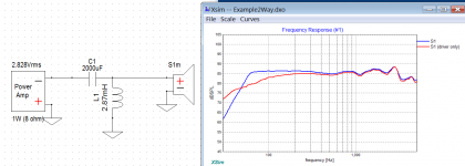
Suppose you we told that the flattening and extending of the woofer response you see was due to:
1) Motional feedback circuitry
2) DSP equalization before the amplifier
3) Addition of a capacitor, which is the subject of this thread
Ignoring the potential distortion reduction by 1) and focusing on the change in the fundamental response, all three of these would have the same relationship between the voltage measured at the voice coil and the measured SPL.
This is a false equivalence because the amplifier drives a woofer thru the same electrical/mechanical converter that produces the damping. In other words, there is only one way to apply a force to the cone and that is sending current thru the voice coil.(ie hands off for now, I’ll return to your hand assessment of damping later)All I'm trying to illustrate about a damped cone, albeit by feel, is that nobody wants loosey circulating ball steering boxes in their car after they've driven with precise rack and pinion steering.
Looking at it from basic physics:
F = ma, where F = BLi + v/Rms + x/Cms
(BLi = motor force, v/Rms = velocity/mechanical damping, x/Cms = excursion/suspension compliance)
Notice that nowhere in the equation of motion does “electrical damping” show up as a separate term.
So, where does the electrical damping force come from? It is built in to the BLi term, where i = current thru the voice coil.
By Ohms law, we know that i = (Va/Re - Vb/Re), where Va = the applied amplifier voltage and Vb = back EMF = vBL.
So the damping portion of the current = -Vb/Re.
Now, add an impedance Z in series with the voice coil. (could be a resistor or a capacitor)
Ii = Va/(Re + Z) – Vb(Re + Z).
Notice that the ratio of driving current to damping current remains unchanged. The Q of the driver is unchanged. The only thing that has changed is the voltage you would measure at the voice coil. Anybody using a 2 channel measurement system that includes a reference probe understands this. With the reference probe attached at the voice coil, it doesn’t matter what impedance you put between the amplifier and woofer; the measured SPL response will be the same. All the series capacitor is doing is forming a passive EQ, changing the voltage applied to the voice coil.
So what about the difference in damping you feel when pushing on the cone? Well, you’ve added another term to the equation of motion…a force that doesn’t act thru BLi and thus doesn’t scale proportionally with impedance in series with the voice coil. So, of course you notice a difference. But, it has nothing to do with the behavior of a woofer driven thru its voice coil.
... The only thing that has changed is the voltage you would measure at the voice coil....
How would you explain the FR plots in post #42? Is somehow some extra voltage is getting to the driver at 60 Hz and less at 20 Hz? Or is the speaker acoustic output peaking at its under-damped resonance?
Surely well beyond my grasp to dispute your algebra, but the T/S model seems to apply when things are working right but is silent when gremlins introduce distortions or the real-world mechanism doesn't precisely match the ideal mechanism posited in the model.
B.
Last edited:
Yup, that is exactly it.How would you explain the FR plots in post #42? Is somehow some extra voltage is getting to the driver at 60 Hz and less at 20 Hz?

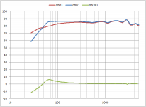
The parts C1 and L1 form an under-damped HP filter providing the roughly +6dB boost transitioning to a -12dB/oct slope at lower frequencies. Green curve on the attached plot is roughly the voltage response you would measure at the woofer connections leading to the VC. No free lunch though, the boost comes with the cost of a corresponding increase in current demand from the amplifier. You might be interested to know that this technique of using under-damped 2nd order filters for EQing is often used to compensate for dipole roll-off with ESLs. I posted EQ response curves for some Martin Logan ESLs here:
Toroids for ESL's
Toroids for ESL's
The basic 50+ year old T/S model definitely comes with caveats and restrictions. It was not intended to capture transducer nonlinearities or interaction of woofer impedance with passive crossover components. Its original purpose was to simplify the mathematics of LF woofer modeling to just a couple of key parameters. This allowed rapid comparison of woofer performance with nothing more than a hand calculator. Most recent modeling programs do still take T/S parameters as inputs, but they are converted/expanded into physical and electrical parameters that can then properly model the EQ effects of passive components placed between amplifier and woofer.… the T/S model seems to apply when things are working right but is silent when gremlins introduce distortions or the real-world mechanism doesn't precisely match the ideal mechanism posited in the model.
Attachments
Is this trick going to increase the power dissipation? Do I need more juice from the amp?
As I understood it works similar to an active highpass with high Q over 0.9?
P.s.: So, all the people that were using amps with single supply and output cap were increasing bottom end extension all this time and not decreasing due to highpass filtering from the cap. 😀
😀
As I understood it works similar to an active highpass with high Q over 0.9?
P.s.: So, all the people that were using amps with single supply and output cap were increasing bottom end extension all this time and not decreasing due to highpass filtering from the cap.
😀
Last edited:
right, the cap compensates the inductivity of the speaker and more current can flow through the voice coil. with Q=1 we can extend half an octave. Then the capacitive effect sets in and the slope is 18dB/oct, so it also high-passes as expected.
Is this trick going to increase the power dissipation? Do I need more juice from the amp?
As I understood it works similar to an active highpass with high Q over 0.9?
The cap also increases the output voltage by 3dB below the resonance, that has the effect of doubling your amp power.
dissipation will increase, but just in that area, above resonance there is a dip and less power is consumed.
You cannot do the same with active filters, they would require a bigger amp.
Last edited:
I had a pair of KEF loudspeakers about 30yrs ago.I think they were KEF Codas that used this technique,Sort of half way house between IB and BR.
Worked well
I was unable to detect any audible deterioration in transient response but there was defo more extension in the bass.
Another bonus for turntable users is a good reduction in subsonic rumble and cone "wobble".
Worked well
I was unable to detect any audible deterioration in transient response but there was defo more extension in the bass.
Another bonus for turntable users is a good reduction in subsonic rumble and cone "wobble".
Can I use a polar electrolytic for this? What's the best way?
One polar cap with + to the amp output, two caps back to back with pluses facing outside, or two caps face to face with minuses facing outside and bias voltage(how much?) applied to the center point?
One polar cap with + to the amp output, two caps back to back with pluses facing outside, or two caps face to face with minuses facing outside and bias voltage(how much?) applied to the center point?
Also does this trick works with Zobel network on the speaker? My crossover is active, so the amp goes directly to the speaker with Zobel soldered on the terminals.
You can use two back to back polar electrolytics but then have to bias the midpoint (a few volts is sufficient). Paralleled non-polar electrolytic caps are probably the best way. You can get oddball values like 700 and 800uF with combinations, while standard polarised aluminum caps restrict you in what values you can use.
There is a formula somewhere on the site that allows you to compute the actual cap value needed.
There is a formula somewhere on the site that allows you to compute the actual cap value needed.
Can I use a polar electrolytic for this? What's the best way?
One polar cap with + to the amp output, two caps back to back with pluses facing outside, or two caps face to face with minuses facing outside and bias voltage(how much?) applied to the center point?
You need a bipolar cap but can use 2 polars of double the required value in series. Either both positiv or negative sides connected, and no other what you call bias.
The DC voltage rating should be at least double the rail voltage of the amp.
Bipolar caps are available as motor-start capacitors with very high voltage ratings.
- Home
- Loudspeakers
- Subwoofers
- Passively-assisted sealed alignments