Grey, are you sure...well probably you are...but just in case, was your file smaller than 800x600?GRollins said:
Grumble, grumble, grumble...
Grey
/Hugo - eagerly waiting for the .jpg 😉
Grey, maybe the graphic files are limited in size AND resolution
but there's nothing said about it
but there's nothing said about it
I understand the issue of Peletiers moving heat from one surface to another. But, does the hot surface need to be cooled? Does the heat removed from the source and that generated by the Peletier device need to be dissapated or does the Peletier device sustain a temperature differential between the two sides? Or, even if it does sustain a temperature differential, is the temperature difference simply brought up to a higher level? Hypothetically speaking, say 5 C one side and 30 C the other and then when the cold surface is brought up against the hot surface does it become something like 25 C one side and 50 C the other.
I have noticed that Peletie devices are often sold with cooling fans. I considered this for a while then I got hooked on the GC thing and haven't considered it much since.
Vic
I have noticed that Peletie devices are often sold with cooling fans. I considered this for a while then I got hooked on the GC thing and haven't considered it much since.
Vic
A peltier is simply a "heat pump"
It literally takes the heat from the component on it's cold surface, and sends it to the hot surface
you absolutely need to cool the hot surface!!! Use it uncooled for half a minute, you'll be surprised. It will heat so much that the powering wires will unsolder them (that hapened on one I had. If it's normal, or if it was bad soldered, I don't know)
Peltiers aren't meant to be used there. You'll have to dissipate even more heat (the transistor's one + the peltier's one)
Peltiers are used for cooling components below the ambiant temperature, something you can't do with classical air cooling. But they require more air cooling on the peltier that without it
If you have difficulties to cool your transistors, adding a peltier will give you even more difficulties
Grey, could you please email the graphic to the webmaster email address and I'll try to work out what is going on ... this is the 2nd report I've had but try as I might, I've been unable to replicate the problem.

It's for those who were upset over the high parts count in the Son of Zen. (Ahem...)
As a fringe benefit, the damping factor is higher and the heat dissipation lower. Distortion will also be somewhat lower, in that followers have 100% local degenerative feedback.
The caveat is that, being a follower, it will require a fair amount of gain from stages upstream, whether they be preamps, active crossovers, or whatever. Like the original SOZ, it will be happiest with a balanced input.
Naturally, you can replace the 8 ohm resistors under the MOSFETs with current sources, which will make things even more efficient, but that's another post for another day.
Grey
GRollins said:It's for those who were upset over the high parts count in the Son of Zen. (Ahem...)
As a fringe benefit, the damping factor is higher and the heat dissipation lower. Distortion will also be somewhat lower, in that followers have 100% local degenerative feedback.
The caveat is that, being a follower, it will require a fair amount of gain from stages upstream, whether they be preamps, active crossovers, or whatever. Like the original SOZ, it will be happiest with a balanced input.
Naturally, you can replace the 8 ohm resistors under the MOSFETs with current sources, which will make things even more efficient, but that's another post for another day.
Grey
Your schematic, with a preamp (say a bosoz), looks to me like a complete amp, but with separated front end and output stage
maybe we could design something "integrated" using this follower and a high gain "preamp"
GRollins said:It's for those who were upset over the high parts count in the Son of Zen. (Ahem...)
As a fringe benefit, the damping factor is higher and the heat dissipation lower. Distortion will also be somewhat lower, in that followers have 100% local degenerative feedback.
The caveat is that, being a follower, it will require a fair amount of gain from stages upstream, whether they be preamps, active crossovers, or whatever. Like the original SOZ, it will be happiest with a balanced input.
Naturally, you can replace the 8 ohm resistors under the MOSFETs with current sources, which will make things even more efficient, but that's another post for another day.
Grey
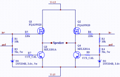
Here is a simple CCS implementation...
Attachments
Hi Mr Nelson!
Sorry for this off topic question, but I never see you online...
Perhaps the cause is the difference between our time!
😉
So, my question is: when we DIY'ers can SEE your Factory from INSIDE? Some pics in the web...
Kindest Regards,
Pedro Martins
Sorry for this off topic question, but I never see you online...
Perhaps the cause is the difference between our time!
😉
So, my question is: when we DIY'ers can SEE your Factory from INSIDE? Some pics in the web...
Kindest Regards,
Pedro Martins
audioPT said:Hi Mr Nelson!
Sorry for this off topic question, but I never see you online...
Perhaps the cause is the difference between our time!
😉
So, my question is: when we DIY'ers can SEE your Factory from INSIDE? Some pics in the web...
Kindest Regards,
Pedro Martins
Instead of trying to steal this thread, just post the question as a new topic, & if Mr Nelson feels up to it, I'm sure he'll add photos.
Nelson Pass said:I think some emitter resistances will be highly appropriate
and make DIY life a lot easier.
Good Idea, though, the initial thread post did ask for the absolute minimum.
Also, with the adition & right module size & heat sink mount, it should be easy to parallel this circuit.
I guess that propeller is spinning again.
maybe I missed something here ... I think there REALLY needs to be some resistors in the emitter legs or this circuit will very quickly go beyond class A, even if those Motorolas are genuine 🙂
Maybe you meant to put R7 and R8 in different places?
mlloyd1
(who doesn't want to see any innocent MJL3281A killed nor anybody injured from fragments of said deveice when it explodes! )
)
Maybe you meant to put R7 and R8 in different places?
mlloyd1
(who doesn't want to see any innocent MJL3281A killed nor anybody injured from fragments of said deveice when it explodes!
)Brian Guralnick said:
Good Idea, though, the initial thread post did ask for the absolute minimum.
Also, with the adition & right module size & heat sink mount, it should be easy to parallel this circuit.
I guess that propeller is spinning again.
mlloyd1 said:maybe I missed something here ... I think there REALLY needs to be some resistors in the emitter legs or this circuit will very quickly go beyond class A, even if those Motorolas are genuine 🙂
Maybe you meant to put R7 and R8 in different places?
mlloyd1
(who doesn't want to see any innocent MJL3281A killed nor anybody injured from fragments of said deveice when it explodes!
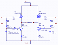
Ok, emitter resistors added.
R7 & R8 in different places? How do you mean?
Attachments
With a BOSOZ or something of that nature wrapped around the outside you'd have a complete, functioning amplifier, as Bricolo noted. The trick is to get enough clean voltage from the front end to do the entire swing for the output. Easy enough for a 50W amp...not too difficult for 100W...it gets challenging if the goal is 600W.
At that point, it becomes a fairly easy task to "X" the circuit. Presto! A poor man's Pass Labs X amplifier. All in two stages and with minimal parts count. Being two stages, it probably doesn't count as a true Zen amplifier any more, but speakers don't care.
Yes, you'll still need a fairly hefty power supply, but at least the circuit won't be burning power through the upper 8 ohm load resistors, and with current sources on the bottom the waste there will be minimized.
More power--or less heat dissipation per output device--is easy. Just parallel the output devices. Add a smallish resistance at the Source of each output. Match the devices; they'll all need to be matched, unfortunately. Like the SOZ, the amp is easily scalable to whatever rail voltage you have on hand or, conversely, to whatever power output you might want.
Just add large heatsinks and stir.
Unless, of course, you need only a teeny-tiny amount of power to run your headphones.
Grey
GRollins said:Match the devices; they'll all need to be matched, unfortunately.
Grey
My source follower design can be modified so it will not need matching of the mosfets & transistors when paralleling. Now, the matching will only be needed in the gain stage, most likely a balanced line stage soz.
- Status
- Not open for further replies.
- Home
- Amplifiers
- Pass Labs
- Pass Son of Zen w/current sources (etc.)