Absolutely🙂 Thats why I only build amps half the year😉Life is too short to spend it being bored, don't you think?
(And go flyfishing the other half;-))
Not being able to design anything decent, I will just have to wait until Nelson or you Grey, comes up with something cool 😉
I guess there is nothing wrong with that approach? 🙂 ??
Steen🙂
I make no claims to having as many ideas as Nelson. I've come up with maybe a half-dozen useful things over the last few years. Nelson does that many in a month.
Last night was a nightmare here at work...I'm hoping to have a few moments of peace and quiet tonight to think something through. (With a baby about the house, I can't think there...) It may be useful, it may not. Like spaghetti, you throw 'em against the wall and see if they stick. Throw enough noodles, you'll eventually find one that hangs there a moment.
Grey
GRollins said:Life is too short to spend it being bored, don't you think?
Sleeping is boring, right ?
Hi,
Nelson, Grey, thank you very much for the support and explanations. I am happy to say that my ZEN V8 with a Mosfet is working, and it sounds very good! Definitely better than my ZEN V3. Its sound is more transparent, clear and very easy on ears. I have built this version because I liked the idea of cascode design, and I just had enough parts in my junk box to try it without spending big money. I know that the design can still be improved, (CCS, regulated PSU, modulated cascode) but hey, as is, it is still damn good!
I strongly encourage all of you, who have built previous Zen variations (1-4) to do this simple modification. Of course the Jfet variant will be even better, but don’t have to wait for the LU1014. If you have a suitable Mosfet, do it now. It’s worth it.
I will make some pics of the finished unit and post them here in the next few days…
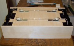
By the way, I have to confess that there is still one problem. However it has nothing to do with the design itself. Since I have built this one in a wooden enclosure, I am experiencing transformer buzzing. (The box is resonant, when you knock on it, it produces a distinctive sound). I am using a 600 W EI tranny. I have to insulate it somehow. Or, maybe I’ll buy a toroid one. Hopefully it won’t buzz that much….
Best regards,
Vix
Nelson, Grey, thank you very much for the support and explanations. I am happy to say that my ZEN V8 with a Mosfet is working, and it sounds very good! Definitely better than my ZEN V3. Its sound is more transparent, clear and very easy on ears. I have built this version because I liked the idea of cascode design, and I just had enough parts in my junk box to try it without spending big money. I know that the design can still be improved, (CCS, regulated PSU, modulated cascode) but hey, as is, it is still damn good!
I strongly encourage all of you, who have built previous Zen variations (1-4) to do this simple modification. Of course the Jfet variant will be even better, but don’t have to wait for the LU1014. If you have a suitable Mosfet, do it now. It’s worth it.
I will make some pics of the finished unit and post them here in the next few days…
By the way, I have to confess that there is still one problem. However it has nothing to do with the design itself. Since I have built this one in a wooden enclosure, I am experiencing transformer buzzing. (The box is resonant, when you knock on it, it produces a distinctive sound). I am using a 600 W EI tranny. I have to insulate it somehow. Or, maybe I’ll buy a toroid one. Hopefully it won’t buzz that much….
Best regards,
Vix
GRollins said:(With a baby about the house, I can't think there...)
Grey
Hey , I have an idea.Maybe some of us could donate to a good babysitter service in Greys area while he works undisturbed churning out ideas for eager diyers.😀
protos said:
Hey , I have an idea.Maybe some of us could donate to a good babysitter service in Greys area while he works undisturbed churning out ideas for eager diyers.😀
maybe ,just maybe, he like to spend some time with his baby ?

Yeah , don´t tell me about not mixing kids and diy.My 3 1/2 year old son likes to come in my workshop while I am tweaking my 550volt tube amp and offers to <help> me fix it.It is hard to keep him away!
Usually I have to bribe him with a colorful resistor or similar so he can go and play with his new toy!
Usually I have to bribe him with a colorful resistor or similar so he can go and play with his new toy!
Hi Vix!
Congratulations!
Could you post your final schematic?
What about the out power? Is it similar to the Zen Lite?
Greets:
Tyimo
Congratulations!
Could you post your final schematic?
What about the out power? Is it similar to the Zen Lite?
Greets:
Tyimo
Alain,
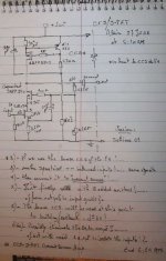
I believe it will work. The only thing I see is that you might want to drive the 1000uF cap from the Source of the JFET to the Gate of the MOSFET with a pot--I am assuming that you are using it in Nelson's 'modulation' scheme. I believe he suggested a value of 100 Ohms or so for the pot, but check his post to be sure.
The resistor next to the 1000uF cap (the one with the ?) can be most any reasonable value. Another 4.7k (like the one in series above it) will do just fine.
Grey
Thanks Grey,
I will modify according to your always good advises.
I had this idea last morning having opened the 2 articles
from AudioXpress in front of me ; the F1 on one side and the JFet ZEN variation #8 on the other side.
The use of the CCS to remove the 2 * 22 Ohms was clear at this time.
It's perhaps the only good ideas I had on this day! {Couldn't sleep all night!}
At 6 AM articles from Nelson are so refreshing, Thanks.
PS: I'll post as soon as I have moded the drawing.
Alain.
Hi Tyimo!
Feel free to use the schematic in the post #288. There are only two small small changes:
1. Remove P2 (20k) and 10 K resistor in series with it. Then, insert a fixed 47 K resistor (from R5 to ground)
2. Insert a 2, 2 K resistor after the input cap.
Use P1 (10K) to adjust the voltage at the Drain of Q2 at about half the supply voltage.
This is the way it works for me. I don't know about the output power, but with Fostex 206E I don't really care. It sounds good!
Regards,
Vix
just few thoughts about Aleph J....if this thread is adequate;
Aleph 30 have two TO-92 thingies per channel;seems that J have 3; this one extra can easily be used as follower for driving half of 2SJ109?
or is that 3th TO-92 thingie also weak for driving 2 gates of IRFs....?
looks like Master invented some perpetuum mobile for that capacitance issue.....
but-I can't see on any pic ,where is CCS for input 2SJ109 LTP?
plain ole resistor?
oh- pictures are too blurred........
I just managed 2 pieces of J109...........
just little addendum to previous post:
looks that cascoding is solution for voltage weakness of Lovoltech fets;
for me also looks that only solution for current weakness of 2SJ109 in LTP of Aleph J is cascading
but- puzzle have too few elements ,at least for mine tooboolar brain
looks that cascoding is solution for voltage weakness of Lovoltech fets;
for me also looks that only solution for current weakness of 2SJ109 in LTP of Aleph J is cascading
but- puzzle have too few elements ,at least for mine tooboolar brain
Attachments
It would not surprise me if it turned out that the single transistor nearest the dual JFET was a CCS connected to the Sources of the JFETs in order to make it a better differential.
If we are to assume that the JFET is, in fact, a 2SJ109, then it would be entirely appropriate for the CCS to be something like, say, a ZTX550. Just for giggles, you could shoot for something like 5-10mA through the CCS, depending on whether the 2SJ109 is GR, BL, or VI.
That should be enough to get you started.
Grey
GRollins said:It would not surprise me if it turned out that the single transistor nearest the dual JFET was a CCS connected to the Sources of the JFETs in order to make it a better differential.
If we are to assume that the JFET is, in fact, a 2SJ109, then it would be entirely appropriate for the CCS to be something like, say, a ZTX550. Just for giggles, you could shoot for something like 5-10mA through the CCS, depending on whether the 2SJ109 is GR, BL, or VI.
That should be enough to get you started.
Grey
couldn't agree more after some thinking;
I just didn't realize that current sum through first stage (LTP) in A30 is just 25 mA...
"just" because I'm still (and always) used on "high current ,low Ri ,high S" approach in my tube fun.
yup-seems that nearest little critter must be simple CCS for Jfet LTP
fortunately-unfortunately - my only two pieces of 2SJ109-s are BL ,not GR😀 ,not V(I)

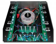
from pic we can see that Nelson use "just" two pairs of bigguns in output (two ,not 3 pieces in active part),certainly to reduce input capacitance of stage by one third, and to make life easier to LTP...
all I need now is little more help from my "resident SS helper " friend Oly,and maybe a pair of 109V(I) to achieve more than 20mA through LTP ;looks to me that 20mA is upper limit for BL iteration (12,5mA ,according to quick look in ECA tables).... and seems that reasonable goal is around 25-30mA....that need checking,regarding noise and dist....
interesting - everyday praxis sometimes seems different than usuall hifi mumbo jumbo......looks that in many posts here (around) some ppl don't like BJT as reg element of any sort (base shot noise etc) ,Nelson use exactly this............
in this moment I'm overwhelmed with pure intelectuall joy,even if fruits are primary from some other's intellect
life is fun,few steps back,few steps forward ,and randommmmmmmmmm......
- Status
- Not open for further replies.
- Home
- Amplifiers
- Pass Labs
- Pass JFET Power Amplifier