That's the kind of falling-all-over-himself review that manufacturers die for. I'm sure that Nelson had to buy a new box of tissues to wipe his tears (of joy) after reading it.
Grey
Grey
GRollins said:That's the kind of falling-all-over-himself review that manufacturers die for. I'm sure that Nelson had to buy a new box of tissues to wipe his tears (of joy) after reading it.
Grey
I'm pretty sure that Nelson is already used to this 😉
hehe- I hope that he'll not read this post

choky said:I'm pretty sure that Nelson is already used to this 😉
There is less than you might think, and I never tire of it
😎
Hello Mr Pass,
If you cared about award that much you'd have start paying for colored ads. On the other hand it's not Zen to have to do that to get an award. 😉
I don't follow the US audio magazines too much so don't kill me for this. The last time I remember an award for PassLabs was the aleph 3.
If you cared about award that much you'd have start paying for colored ads. On the other hand it's not Zen to have to do that to get an award. 😉
I don't follow the US audio magazines too much so don't kill me for this. The last time I remember an award for PassLabs was the aleph 3.
Nelson Pass said:There is less than you might think, and I never tire of it
For some there is none, and they are probably very tired of it.
??? What is ¡°there¡±
??? What is ¡°less¡±
??? What is ¡°some¡±
??? What is ¡°none¡±
??? What is ¡°it¡± of ¡®tire of it¡¯
I¡¯m very bad in language.
And, I understand only Konglish. :flush:
Regards
jh
??? What is ¡°less¡±
??? What is ¡°some¡±
??? What is ¡°none¡±
??? What is ¡°it¡± of ¡®tire of it¡¯
I¡¯m very bad in language.
And, I understand only Konglish. :flush:
Regards
jh
Hi!
In post #235 Tyimo asked if his schematic is ok, but there was no answer. Maybe it was obvious, but for some of us it is somewhat less obvious.
So, basically I am repeating the same question. To be more precise: If I decide to build a ZV8, using schematic on figure 10 (with 6db of feedback), but I want to use a mosfet instead of a jfet, then:
1.It is possible to use exactly the same schematic, just replace the jfet with mosfet.
2.There should be a resistor (100 Kohm perhaps) connecting the drain of Q2 with the gate of Q1.
Which one is correct: 1 or 2 ?
😕
I know that this question seems stupid, but this is really confusing me.
Thanks a lot,
Viktor
Vix,
I looked at the post you were referring to but it's a PCB, not a schematic so I'm not sure what you're asking.
1) I'm afraid that you can't use the Zen #8 schematic as-is with a MOSFET on the bottom. The LU1014D is a depletion device, which means that its Source needs to be more positive than its Gate. The IRF MOSFETs are just the opposite--their Gates need to be more positive than their Sources.
2) A simple resistor between the Gates of Q1 and Q2 will not bias the lower MOSFET correctly.
There are several ways that you can bias the lower MOSFET. The way I would do it would be to add a lower rail and go from there. Nelson's way, I suspect, would be to use a capacitor to decouple the input and use a resistive divider not unlike the one used in some of the earlier Zens to apply bias to the Gate. The easiest thing at that point would be to used a fixed resistive divider to pin the Gate of the cascode device at some arbitrary voltage, like 15V, or perhaps even higher.
You would need higher rails to get the same wattage, as the Vgs of the MOSFET will eat up a little more of the existing rail. Also, the higher you run the voltage at the Gate of the cascode, the higher the rail will need to be.
Grey
Hi,
Grey, thank you very much. That is the answer I was looking for.
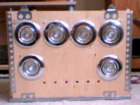
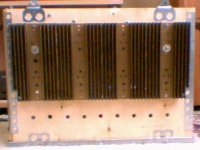
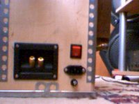
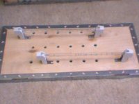
I started working on it. In fact, I have managed to build an "F2-Lite" (if I can call it that way). I was not entirely satisfied, took out a PCB , and will modify it as ZEN V8, but with a mosfet. At least until I get a pair of Jfets...
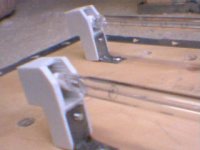
I am attaching some (poor quality) pictures, just to let people see what it looks like. When completed, I will borrow a decent camera and I hope I will show it in a full light😀
Concerning the lightbulbs, at first I tried the solution with 6 ceiling halogen lamps (front side). There were 3 (20w, 12v) lamps connected in series, per channel. However, the voltage accross one lamp was around 9v, meaning they were quite bright, and hot. Only then I realized that these lamps release most of the heat on the backside. So the inside of the enclosure was getting too hot. I disconnected them, and I bought two halogen sticks (1500w, 220w) and, since they are mounted outside, on the top , there was no heating problem....
Anyway, have a look....
Thank you very much,
Viktor
Grey, thank you very much. That is the answer I was looking for.
I started working on it. In fact, I have managed to build an "F2-Lite" (if I can call it that way). I was not entirely satisfied, took out a PCB , and will modify it as ZEN V8, but with a mosfet. At least until I get a pair of Jfets...
I am attaching some (poor quality) pictures, just to let people see what it looks like. When completed, I will borrow a decent camera and I hope I will show it in a full light😀
Concerning the lightbulbs, at first I tried the solution with 6 ceiling halogen lamps (front side). There were 3 (20w, 12v) lamps connected in series, per channel. However, the voltage accross one lamp was around 9v, meaning they were quite bright, and hot. Only then I realized that these lamps release most of the heat on the backside. So the inside of the enclosure was getting too hot. I disconnected them, and I bought two halogen sticks (1500w, 220w) and, since they are mounted outside, on the top , there was no heating problem....
Anyway, have a look....
Thank you very much,
Viktor
Attachments
Vix said:Hi,
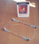
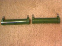
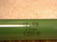
Stefano, you mean 75 Ohm resistors, like these? 🙂
Yes , guess that 10 watt is ok
So, in 28 pages, we've discussed options for Q1, which has been resolved by the group buy, talked a bit about Q2 and a few other topics. All good reading, but, what I want to know is how to get my hands on a set of those way 😎 heatsinks on the F3.
Since I strongly suspect I already know the answer to that (and since I can't afford an F3), any advice on what to look for and/or possible sources would be most appreciated.
I realize that's probably old hat for most of you. This would be my first DIY amp.
Thanks.
Paul Ebert
Since I strongly suspect I already know the answer to that (and since I can't afford an F3), any advice on what to look for and/or possible sources would be most appreciated.
I realize that's probably old hat for most of you. This would be my first DIY amp.
Thanks.
Paul Ebert
Huh, maybe I ought to do a buy on them. At least I wouldn't have to match the bloody things.
Actually, I have my eye on a heatsink supplier. I've been meaning to contact them to see what their prices are like once you get past the one-to-ten quantity.
Grey
Actually, I have my eye on a heatsink supplier. I've been meaning to contact them to see what their prices are like once you get past the one-to-ten quantity.
Grey
Well, Grey, while that might be an appreciated solution, it seems way beyond the call given what you're already doing.
At this point, I guess what I'm asking for is help specifying a heatsink. I believe it needs to dissipate about 100 watts (assuming one per channel). Is that correct? So, if I want it to rise 20 degrees C above ambient that would mean a thermal resistance of 0.2 degrees C/watt. Is that a reasonable figure?
I've done some looking on the Thermaflo website and a heatsink that can dissipate 100 watts with a 20 degree C rise is huge. Like 8" tall by 27" long with 2" fins. If that's what it takes, then that's what it takes, but this doesn't seem right. The F3 sinks certainly aren't that big.
Or are the Thermaflo heatsinks just not very efficient?
Thanks.
Paul
- Status
- Not open for further replies.
- Home
- Amplifiers
- Pass Labs
- Pass JFET Power Amplifier