Re: How would a similarly configured MOSFET or Darlington fare?
haven't built one yet but the mosfet version simulated really well in spice, with flat frequency response way over 100khz (but with a hump at just shy of 1mhz), and minimum phase shift at high frequencies - from that perspective, this amp beats out the plh.
I also tried to use a small signal bjt to drive Q1 and it has no advantage that I can see of over a mosfet.
Petter said:Adjusting the circuit to better suit other types of devices, especially MOSFET, how would such a beast measure?
haven't built one yet but the mosfet version simulated really well in spice, with flat frequency response way over 100khz (but with a hump at just shy of 1mhz), and minimum phase shift at high frequencies - from that perspective, this amp beats out the plh.
I also tried to use a small signal bjt to drive Q1 and it has no advantage that I can see of over a mosfet.
An original prototype of the F3 used a similar circuit with a
Mosfet, and it made it out to 100 KHz, but the distortion was
about 3 times higher.
Mosfet, and it made it out to 100 KHz, but the distortion was
about 3 times higher.
Can we use an Aleph current source instead of the light bulbs?
Would that make an F3 then? - just asking.
Would that make an F3 then? - just asking.
Some weeks ago I started a thread regarding the "Ultra-Linear" topology from tube engineering years ago. I beleive the JFET circuit and modulation, like Nelson is introducing, is exaclty what I was hopping to find out more about... Thanks Nelson. 😀 And of coarse the rest of you too 😀 😀 😀
Is this a "variation" on the ultra linear tube idea?
Is this a "variation" on the ultra linear tube idea?
just quickee from me-ultra linear is negative feedback;
tonight I'll look at Nelsons drawings to see is it same case

tonight I'll look at Nelsons drawings to see is it same case
Hi Nelson,
Before I think about any plan for homework, I would like to understand what the cascode is. Is it right if I think that the +/- V-I slopes meet into a flat curve and the modulation is to adjust degrees of the +/- slopes? Thanks.
Regards
jH
Before I think about any plan for homework, I would like to understand what the cascode is. Is it right if I think that the +/- V-I slopes meet into a flat curve and the modulation is to adjust degrees of the +/- slopes? Thanks.
Regards
jH
lohk said:Can we use an Aleph current source instead of the light bulbs?
Would that make an F3 then? - just asking.
The F3 prototype mentioned will probably not become a real
product. It used a constant current source, but yes you
can easily substitute a constant current source or an Aleph
current source, or a coil.
jh6you said:Before I think about any plan for homework, I would like to understand what the cascode is. Is it right if I think that the +/- V-I slopes meet into a flat curve and the modulation is to adjust degrees of the +/- slopes?
As you may know I wrote an article once on cascoding which
appeared in Audio Magazine many years ago, and which can
be seen at www.passdiy.com (I think).
In any case, The idea is that the gain of the device increases
with current, and increases with voltage. Ideally we want the
gain to be constant, which would make it distortionless. So
when we examine the voltage/current load line of a linear
amplifier, we see that for a resistive load the voltage across
the device decreases as the current increases, and so by
choosing the load line carefully, we have an opportunity to
cancel some nonlinearity in the gain device. This technique
appears to be most popular with triodes.
😎
so where can you purchase these JFETS?
...for some reason i don't think Lovoltech is going to be amused
when i call asking for less than 10 pieces 🙂
...for some reason i don't think Lovoltech is going to be amused
when i call asking for less than 10 pieces 🙂
Why not connect top of R5 to Vcc instead of to C1?
I simulated it and it seems to work.
BTW will any N-channel IRF VFET work as Q2?
Cheers,
Tom
I simulated it and it seems to work.
BTW will any N-channel IRF VFET work as Q2?
Cheers,
Tom
Why not connect top of R5 to Vcc instead of to C1?
dc feedback -> more stable working point
moe29 said:so where can you purchase these JFETS?
...for some reason i don't think Lovoltech is going to be amused
when i call asking for less than 10 pieces 🙂
When you want less than 10 pieces, they're called "samples." 😀
se
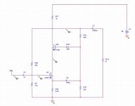
tmblack said:BTW will any N-channel IRF VFET work as Q2?
in my simulation it seems to be quite insensitive to what Q2 is. Here is mine, biased at about 1.7a runnging on two irfp140.
BTW, if you replaced the 11ohm resistor / lightbulb with a CCS, it will almost double the output voltage swing. so maybe the way to go is with three IRF devices, 🙂
Attachments
flg
this comparison to ultra linear mode seems very sensible to me.
Didn't think about it.
Goood point.
this comparison to ultra linear mode seems very sensible to me.
Didn't think about it.
Goood point.
Steve Eddy said:When you want less than 10 pieces, they're called "samples."
It's my understanding that I currently have the world supply of
this part, and mine came directly from Taiwan. but they are
making more, and this is not the only part they offer.
I have emailed them inquiring as to what distribution they might
be able to arrange for retail sales, as their order minimum is
2500 pieces. I'll let you know what they say.
Nelson Pass said:It's my understanding that I currently have the world supply of
this part, and mine came directly from Taiwan. but they are
making more, and this is not the only part they offer.
I have emailed them inquiring as to what distribution they might
be able to arrange for retail sales, as their order minimum is
2500 pieces. I'll let you know what they say.
Hell, why not just distribute them yourself? Your power JFET piece should stirr up enough interest to make that viable don't you think? Unless you just don't want the hassle of course.
se
Referencing previous posts, here's an example how much
distortion cancellation you can enjoy by modulating the cascode.
The top is the stock curve without feedback. The bottom is with
the load line on the JFET chosen to maximally cancel distortion,
leaving only 3rd harmonic. The distortion figures are flat across
the audio band.
Why don't I just post the right values, you ask? The optimal
figures are dependent on the device itself, and the voltage
across the device. Figures which give the best low power
numbers may cut into the higher power performance. This is a
technique for those of you with distortion analyzers.
Modulated Cascode.....has a nice ring to it.
😎
Attachments

Nelson Pass said:
It's my understanding that I currently have the world supply of
this part, and mine came directly from Taiwan. but they are
making more, and this is not the only part they offer.
I have emailed them inquiring as to what distribution they might
be able to arrange for retail sales, as their order minimum is
2500 pieces. I'll let you know what they say.
That's a way to throw off the competition for a second or two.
Seconding SE: Could you turn yourself into the current world distributor for us diyer until this gets settled? Pretty please?
I will need two. Sorry three. I will want to duplicate your burnup experiment and hear what 'nothing' sounds like. 😉
I sent Lovoltech an email yesterday asking for samples. No reply yet.
Sigurd
Sigurd
Steve Eddy said:
When you want less than 10 pieces, they're called "samples." 😀
se
Thank you Nelson for the xtra informations.
By the way, I am jealous as you in www.firstwatt.com look really xexy. 😀
Regards
jH
By the way, I am jealous as you in www.firstwatt.com look really xexy. 😀
Regards
jH
- Status
- Not open for further replies.
- Home
- Amplifiers
- Pass Labs
- Pass JFET Power Amplifier