I was amused when I suggested cascoding in the original power JFET thread and received a rather dismissive reply from another user in response. I dunno...seemed rather obvious. Perhaps he wasn't familiar with the early Threshold stuff.
I can't say that I'm comfortable with the case, but beggars can't be choosers. It might be worthwhile in some installations to attach the tab directly to the heatsink and take the signal from the heatsink. Granted, it's inconvenient, but it would allow for better heat transfer. Live heatsinks, especially since it's only a few volts, are not that bad a problem if you plan ahead. Obviously the MOSFET would need to be on a different heatsink, but that's not all that bad an idea anyway, given that it's going to be dissipating the lion's share of the heat.
Grey
Nelson,
Figure 7 - Q1 VD should be 4.3 V and not .43 V according to your text. What is the minimum practical limit for the cascode voltage of the JFET?
Thanks for the article.
[edit] Never mind, the voltage dictates the current so it's a matter of bias...
--
Danny
Figure 7 - Q1 VD should be 4.3 V and not .43 V according to your text. What is the minimum practical limit for the cascode voltage of the JFET?
Thanks for the article.
[edit] Never mind, the voltage dictates the current so it's a matter of bias...
--
Danny
Hallo
Thank you for answering my doubts, Jan did put it in better words.
Yes, this makes sense.
Kind of parametric linearisation?
This is clever, most 'harmless' way to linearize, but with JFETs it will demand much patience and equipment too to measure curves of Vds-Id, transcondectance.... Otherwise significant cancellation of distortion will probably be just wishes and hopes. Not for home-DIY I think. Nor mass production. 🙂 Am I right?
Does it also linearize in-built capacitances?
Thanks again
I've learned something new.
Thank you for answering my doubts, Jan did put it in better words.
Nelson Pass said:
As to the positive feedback, the modulation is similar to "muting"
the cascode. Some small variation is allowed through, but it
works to slightly decrease the voltage across the JFET on the
negative output swing and increase it on the positive, running
counter to the natural tendency of the transconductance to
increase at higher current and decrease at lower. This gives
some cancellation of the two forms of nonlinearity, which is what
I was referring to when I mentioned working the triode load-line.
😎
Yes, this makes sense.
Kind of parametric linearisation?
This is clever, most 'harmless' way to linearize, but with JFETs it will demand much patience and equipment too to measure curves of Vds-Id, transcondectance.... Otherwise significant cancellation of distortion will probably be just wishes and hopes. Not for home-DIY I think. Nor mass production. 🙂 Am I right?
Does it also linearize in-built capacitances?
Thanks again
I've learned something new.
GRollins said:I was amused when I suggested cascoding in the original power JFET thread and received a rather dismissive reply from another user in response.
does that make you question some of the "expert advices" one receives here? 🙂
As part of the PLH excercise, i went through the old thread on JLH on the solid state forum and found a huge discussion where "experts" vehemently denied a MOSFET version of the JLH could have worked, and presented some sound scientific arguments how it couldn't have worked.
I guess Nelson's PLH must be a fake then, 🙂.
On the cascading amplifier, I just built on yesterday on spice and it is quite an interesting amplifier: very simple, high gain (relatively speeking) and reasonably good performance. Definitely a notch above the SE versions.
I think you should try exploring that a little further.
Indeed, having build a MOSFET JLH amp about a year ago (?), i do remember the discussion.
That discussion was somehow a bit polluted 😉
That discussion was somehow a bit polluted 😉
put much attention to Vds-Id curves, comparisons to triodes, pentodes... if final result is cascoded JFET
In fact there is some load line action in the amp by virtue of the limited transconductance of Q2, and we can easily modulate it further.
play with resistor in series with C2
----
"a nice person on the Pass Labs Forum" 😎
There are a few people here that I read with great intrest. Nelson, of course, John Curl (who also rates an 'of course'), Charles Hansen (ditto), Scott Wurcer, and a few others.
There are others whose posts I read simply because I like them as people.
The rest...I take some with a grain of salt, others with a pound. Anyone who is in this for what is known in author circles as "ego-boo" (i.e. ego boost) I disregard entirely.
Grey
There are others whose posts I read simply because I like them as people.
The rest...I take some with a grain of salt, others with a pound. Anyone who is in this for what is known in author circles as "ego-boo" (i.e. ego boost) I disregard entirely.
Grey
tschrama said:Indeed, having build a MOSFET JLH amp about a year ago (?), i do remember the discussion.
it is amazing how can the "experts" got it so wrong in asserting that such a beast wouldn't work when it does in real life, and when it came from a small potato rather than a big dog like Nelson. I don't see any of those "experts" here arguing with Nelson that his PLH wouldn't work, as those experts did in the JLH thread.
Why? I guess is that those experts really don't know what they think they know and they judged the amplifiers on who their constructors are, not on sound scientific theories and facts.
GRollins said:"ego-boo" (i.e. ego boost)
Isn't it quite sad a person would resort to the internet to get satisfaction they don't have in the real world?
I figured that Grey was the most likely candidate to build the
JFET amp before me, as he clearly had the interest and
capability. What he probably didn't have is my purchasing
manager.
😎
JFET amp before me, as he clearly had the interest and
capability. What he probably didn't have is my purchasing
manager.
😎
dimitri said:play with resistor in series with C2
----
"a nice person on the Pass Labs Forum" 😎
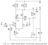
And since you are such a nice person, here is the modulation
technique I have tried.
whoops, wrong schematic - just a minute.....
And since you are such a nice person,
😀 actually I cited the first line of your zv8_power_jfet.pdf

http://www.diyaudio.com/forums/showthread.php?postid=686567#post686567
here is the modulation technique I have tried

Coolllllish ... 😎 very cool ... Aha... this can be done to a stock Zen amplifier too I guess  ?
?
Not being very experienced in drawing load-lines etc etc I wonder if that would work too?
? Not being very experienced in drawing load-lines
etc etc I wonder if that would work too?Nelson Pass said:OK here we go.....
😎
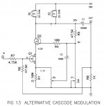
Nelson Pass said:Here's another one - they both work.
😎
Both didn't make it in the sound department? As apparently both didn't make the cut in the final doc...or both presented more "opportunities"?
There are a few people here that I read with great intrest. Nelson, of course, John Curl (who also rates an 'of course'), Charles Hansen (ditto), Scott Wurcer, and a few others.
Anyone who is in this for what is known in author circles as "ego-boo" I disregard entirely.
Subscribe to your opinion, Grey, you know what I do – simple add the person, which irritates me to ignore list
Blues said:Both didn't make it in the sound department? As apparently both didn't make the cut in the final doc...or both presented more "opportunities"?
They present more opportunities, but I decided that they might
be too much of a good thing for people without scopes and
distortion analyzers.
On the other hand, Figure 13 is probably pretty safe with a P2
value of 100 ohms or so.
😎
the amps (figure 12 and 13) can also be made with just two mosfets as well: except that you will have to bias the bottom one slightly different. Rather than picking up the feedback from the speaker terminal, I feed the signal from the D of Q2 and feed it back to G of Q1. Worked quite well and saved one power jfet.
How would a similarly configured MOSFET or Darlington fare?
Adjusting the circuit to better suit other types of devices, especially MOSFET, how would such a beast measure?
That would be a very interesting comparison (as would a listening test).
Petter
Adjusting the circuit to better suit other types of devices, especially MOSFET, how would such a beast measure?
That would be a very interesting comparison (as would a listening test).
Petter
- Status
- Not open for further replies.
- Home
- Amplifiers
- Pass Labs
- Pass JFET Power Amplifier