I have only bought the "B" grade of 546/546 and "C" of 550/560. I have not measured and compared the two.
It is more of a question of tradeoffs. If I pick the high breakdown versions should I expect lower beta? (Yes?) If I pick the higher beta versions is there perhaps lower early voltage? What other trade offs will exist? Which are tradeoffs between different designs versus tradeoffs between different selections of the same design?
Are there other tradeoffs? Is the higher gain of the "C" or "-40" selection free? [Is it a selection or is it a process/version/doping/recipe difference?] Are there tradeoffs? In this case I am interested in whether the "C" or "-40" higher hFE is correlated to lower linearity or not. I don't know however my general thought is that nothing is free in terms of tradeoffs in semiconductors/transistors. But perhaps in this case the high beta selection from the same transistor design is not detrimental to linearity?
Threads about tradeoffs that are part of the reason I ask:
Questions about Transistors with high beta (hfe) up to 3000 without Darl.-Topology
Is it ever desirable to have *low gain* transistors?
And this thread:
Measuring Beta vs Icollector for a few small signal PNPs
(Look at the 560C in the first post.)
Last edited:
So if you want to use those measurements as reference, and there is no reason not to, then you should just use BC327-40, 337-40, not ?
As Jam mentioned early, you should put more focus on the FETs than on the BJTs. Especially in a 4-BJT current mirror.
FETs have a lot more variation.
Patrick
As Jam mentioned early, you should put more focus on the FETs than on the BJTs. Especially in a 4-BJT current mirror.
FETs have a lot more variation.
Patrick
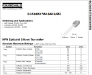
So to be more specific I have attached a screen shot of the first page Datasheet of the family of:
1. Fairchild BC546 547 548 549 550
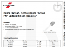
2. Fairchild BC556 557 558 559 560
Now it is not the exact data that I want but the hFE versus current of the 560 seems to be very non-linear while the 556B & 556C is much better. (I wish I had more/better data to point to but this is what is quickly accessible. I wish the 556B and 556C data continued to higher currents.)
Link for BC560C: Measuring Beta vs Icollector for a few small signal PNPs
2nd Independent Link for BC560C: Measuring Beta vs Icollector for a few small signal PNPs
Link for BC556B & BC556C (and also look at the datasheet): Measuring Beta vs Icollector for a few small signal PNPs
I will keep looking for higher current BC556B & BC556C curve traces.
Perhaps it is the difference in the BC560C member of the family and not applicable to the other members of the family? Perhaps the ?process? ?recipe? change for the low noise BC560C significantly degraded hFE linearity? (Strong base doping/lower base sheet resistance? Does anyone know what the process difference is for the BC560 & BC550 versus the rest of the family?)
1. Fairchild BC546 547 548 549 550
2. Fairchild BC556 557 558 559 560
Now it is not the exact data that I want but the hFE versus current of the 560 seems to be very non-linear while the 556B & 556C is much better. (I wish I had more/better data to point to but this is what is quickly accessible. I wish the 556B and 556C data continued to higher currents.)
Link for BC560C: Measuring Beta vs Icollector for a few small signal PNPs
2nd Independent Link for BC560C: Measuring Beta vs Icollector for a few small signal PNPs
Link for BC556B & BC556C (and also look at the datasheet): Measuring Beta vs Icollector for a few small signal PNPs
I will keep looking for higher current BC556B & BC556C curve traces.
Perhaps it is the difference in the BC560C member of the family and not applicable to the other members of the family? Perhaps the ?process? ?recipe? change for the low noise BC560C significantly degraded hFE linearity? (Strong base doping/lower base sheet resistance? Does anyone know what the process difference is for the BC560 & BC550 versus the rest of the family?)
Attachments
So if you want to use those measurements as reference, and there is no reason not to, then you should just use BC327-40, 337-40, not ?
I was actually thinking of ordering some BC327/337 for future projects. Now -25 or -40? At this point I assume -40 but I wonder if there is any tradeoff I should be aware of.
As Jam mentioned early, you should put more focus on the FETs than on the BJTs. Especially in a 4-BJT current mirror.
FETs have a lot more variation.
Patrick
Sure. Unfortunately it is hard to get those FETs and when mine arrive we will see what choice (if any) we have between the small quantity available.
If you do not want to pay the price for Toshiba JFETs, you should build an all BJT circuit, like the Pioneer Super Linear.
Or, use SMD N-JFET (2Sk209GR) input stage rather than complementary.
The Pioneer Super Linear Circuit
UDNeSS, or You don't need Semisouth's
Patrick
Patrick
Or, use SMD N-JFET (2Sk209GR) input stage rather than complementary.
The Pioneer Super Linear Circuit
UDNeSS, or You don't need Semisouth's
Patrick
Patrick
One way or another I will build the HPA-1. I have one unused preamp board with the Toshiba JFETs. I don't want to disassemble it yet. I will see what arrives. Otherwise maybe I can find someone willing to trade for the PCB or something else. I will have five HPA1 PCB and five WHAMMY PCB when they arrive. It would have been nice if Toshiba had made a complement for the 2SK209.
Last edited:
kozard,
Matching helps reduce 2nd harmonic as Patrick says but sonically is it as important........well not as much as you think but the experiment will lead to a better understanding of the circuit.
Please send me a personal e-mail I may have something useful for you.
Jam
Matching helps reduce 2nd harmonic as Patrick says but sonically is it as important........well not as much as you think but the experiment will lead to a better understanding of the circuit.
Please send me a personal e-mail I may have something useful for you.
Jam
Hello Jam,
I am starting on the regulator for my HPA1 build. I used the online photos and Jeff's work as a starting point.
Purely due to available parts and necessary economy I was wondering if the following changes would be a bad idea. On one hand I hesitate to ask since I read that the HPA1 supply went through many revisions to get right. However I don't ask due to any desire to redesign. I ask only because I don't presently have dual secondary transformers or those specific Sanken Darlington transistors.
First, is it correct to assume that the Sanken Darlington's are a critical element of the design that should not be changed? If so I will endevour to obtain them. As a temporary measure what do you think of the following temporary substitutes?
1. Genuine disassembled Sanken D2390/B1560 from an old receiver.
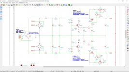
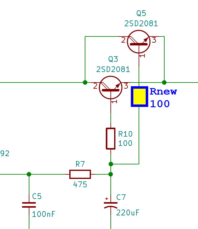
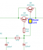
2. Make a discrete Darlington using the 200 Ohm and 2k Ohm values from the Sanken 2SD2081 datasheet and Toshiba 2SC5200/2SA1943 or Sanken MN130S/MP130S and 2SD669/2SB649 or Toshiba TTC004B/TTA004B? (Schematic attached.)
Second, the transformer is a bit of an issue since ordering a custom transformer is out of the question. I presently have a 150VA toroid (surplus from an unknown audio manufacturer) and also a rather large 32VAC 370VA disassembled (Onkyo) EI core audio/receiver transformer. (Due to the higher voltage I have used a separate pre-regulator in the past.)
However both transformers are single secondary center tapped transformers.
For the future I could look at ordering something like an Antek dual secondary Toroid.
What sort of performance issues can result from changing the transformer type used?
I have attached my draft schematic from KiCad. I plan on making the regulator on a separate PCB so that I can try it with my other projects such as the op-amp supply for my DAC. Also a separate PCB greatly lowers the cost when I can fit it into the "special offer" size limits of the PCB manufacturers.
I am starting on the regulator for my HPA1 build. I used the online photos and Jeff's work as a starting point.
Purely due to available parts and necessary economy I was wondering if the following changes would be a bad idea. On one hand I hesitate to ask since I read that the HPA1 supply went through many revisions to get right. However I don't ask due to any desire to redesign. I ask only because I don't presently have dual secondary transformers or those specific Sanken Darlington transistors.
First, is it correct to assume that the Sanken Darlington's are a critical element of the design that should not be changed? If so I will endevour to obtain them. As a temporary measure what do you think of the following temporary substitutes?
1. Genuine disassembled Sanken D2390/B1560 from an old receiver.
2. Make a discrete Darlington using the 200 Ohm and 2k Ohm values from the Sanken 2SD2081 datasheet and Toshiba 2SC5200/2SA1943 or Sanken MN130S/MP130S and 2SD669/2SB649 or Toshiba TTC004B/TTA004B? (Schematic attached.)
Second, the transformer is a bit of an issue since ordering a custom transformer is out of the question. I presently have a 150VA toroid (surplus from an unknown audio manufacturer) and also a rather large 32VAC 370VA disassembled (Onkyo) EI core audio/receiver transformer. (Due to the higher voltage I have used a separate pre-regulator in the past.)
However both transformers are single secondary center tapped transformers.
For the future I could look at ordering something like an Antek dual secondary Toroid.
What sort of performance issues can result from changing the transformer type used?
I have attached my draft schematic from KiCad. I plan on making the regulator on a separate PCB so that I can try it with my other projects such as the op-amp supply for my DAC. Also a separate PCB greatly lowers the cost when I can fit it into the "special offer" size limits of the PCB manufacturers.
Attachments
Hi Kozard,
Dual secondries nd two bridges can help but in this application the difference is minimal.
As for devices go a package will be on the way to you next week.
Jam
Dual secondries nd two bridges can help but in this application the difference is minimal.
As for devices go a package will be on the way to you next week.
Jam
Last edited:
Hi Kozard,
Suggest you go thru Salas' L-Adapter project as this will save you some time 're-inventing the wheel'
Suggest you go thru Salas' L-Adapter project as this will save you some time 're-inventing the wheel'
I have started to layout the HPA1 regulator. (My HPA1 amplifier boards have shipped and should arrive in a couple of weeks.)
One of my objectives is to fit it into the 10cm by 10cm $2 JLCPCB special offer so that everyone can enjoy the HPA1 regulator either with the HPA1 clone or with other circuits. (I plan to try it with my DAC to supply the I/V op-amps.)
Fitting it into 10cm by 10cm isn't easy. I kept 35mm snap-in capacitors since that is the most common footprint for 10,000uF 50V. But that is tough to get into 10cm by 10cm.
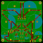
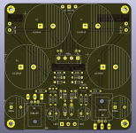
I intend to use all the same original components. The pass transistors are under the PCB (the aluminum chassis will be the heatsink). I am putting footprints for the original Sanken part numbers which are TO-220. However I am also putting a larger footprint since I will have left over PCB (5 for $2 at JLCPCB) and I may want to use this regulator for other projects in the future.
This is just a first draft/first parts placement. Please let me know how I can improve it and how I can learn more.
One of my objectives is to fit it into the 10cm by 10cm $2 JLCPCB special offer so that everyone can enjoy the HPA1 regulator either with the HPA1 clone or with other circuits. (I plan to try it with my DAC to supply the I/V op-amps.)
Fitting it into 10cm by 10cm isn't easy. I kept 35mm snap-in capacitors since that is the most common footprint for 10,000uF 50V. But that is tough to get into 10cm by 10cm.
I intend to use all the same original components. The pass transistors are under the PCB (the aluminum chassis will be the heatsink). I am putting footprints for the original Sanken part numbers which are TO-220. However I am also putting a larger footprint since I will have left over PCB (5 for $2 at JLCPCB) and I may want to use this regulator for other projects in the future.
This is just a first draft/first parts placement. Please let me know how I can improve it and how I can learn more.
Attachments
-
 KOZARD HPA1 Regulator First Draft Placement.png90.3 KB · Views: 354
 -
 KOZARD HPA1 Regulator First Draft Placement 3D.png111 KB · Views: 320
 -
 KOZARD HPA1 Regulator First Draft Placement Back.png40.2 KB · Views: 344
 -
 KOZARD HPA1 Regulator First Draft Placement Bare.png56.6 KB · Views: 323
 -
KOZARD HPA1 Reg Schematic.PDF52.6 KB · Views: 232
Last edited:
The caps *could* hang off the sides of the board a bit (a few mm?) leaving you with a bit more space.
I try to have all my electrolytics pointing one way on a board. Minimizes build errors.
Of course if you're really careful it doesn't matter -- but past experience has shown that I'm not. 😉
Of course if you're really careful it doesn't matter -- but past experience has shown that I'm not. 😉
Best practice in discrete component circuit design is to add "ballast" resistors in series with every base, or every emitter, when transistors are connected in parallel. The Google search term is "current hogging" and I am not making this up.
_
_
Attachments
Last edited:
Thanks Mark.
The two are not intended to be used in parallel. Instead they are "either/or". One is TO-220 case size and the other is TO-3P/TO-247 case size if someone has the larger case Darlington in their parts bin but not the TO-220. I intend to use the original TO-220 size but I will have some extra PCB left over. If I use a left over board for a different project I might only have TO-3P/TO-247 case size Darlington available/left in my stock. Hence the optional larger footprint on the PCB.
I will add notes to the schematic to make that clear.
Last edited:
I would emphasize what Jeff, A Jedi and Mark mentioned above about straightening up the cap orientation and such...
Adding to that, I would further suggest that the pcb copper area between C1 and C2 should be short, and continuous for the higher current charging pulses, (no other tracks between them), and move your KBL401 'block bridge' and the fuses to the outside edge so can add a heatsink if required and/or replace fuses (it's going to get hotter in the middle of the caps) - while doing that, move the 2R2 resistors away from the caps too (capacitors hate getting hot)
Unless your pcb is only ever going to be mounted vertically on the heatsink, the transistors Q3-Q6 options are also going to add heat to the pcb so you mignt consider moving these to the outside edge of the board even at the 'downside' of needing more chassis space.
... my 2 cents
The intention is for me to mount the 10cm x 10cm HPA-1 and the 10cm x 10cm HPA-1 Regulator in a 20.3cm by 14.5cm aluminum chassis where the floor chassis is the heatsink. Thus the space is very tight. The way the chassis is made each half is like a 20.3cm by 21.3cm aluminum heatsink. (The 21.3cm side is U shaped.) I think that is a good size for the required dissipation.
I have attached draft version 0.2 where I have rotated the capacitors and adjusted a few other things. Later today I will see if I can find a way to move the bridge and/or the pass transistors. The fuses are likely to be something like 1A polyfuse. The HPA-1 Class A bias is 2x100mA. With about 10V across the pass transistors that is 2W dissipation for each of the pass transistors. The 2.2Ohm resistor in the CRC filter will see about 0.44V at 0.2A or about 88mW for a 3W resistor. I expect the surface temperature of the resistors will be low. I did move the resistors further away from the capacitors. I expect the surface temperature of the 4A bridge to be low at about 0.2A. However I will look at an alternative layout (if possible) later today to move that.
I also added ground pour to the top (it was already on the bottom). Is that a good or bad idea?
Attachments
Last edited:
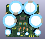
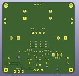
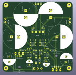
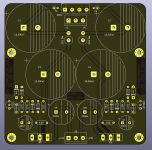
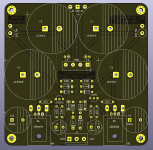
Worked on a draft version C (first images) and a draft version B.
Please make any suggestions for improvements. B might fit my chassis better. Version C incorporates more of the suggested changes.
Please make any suggestions for improvements. B might fit my chassis better. Version C incorporates more of the suggested changes.
Attachments

- Home
- Amplifiers
- Pass Labs
- Pass HPA-1, what do we know?