Hi, Coffin,
I notice that if the output of the Single-End OPT is open,
The Single-End OPT just like a huge inductor.
The counter-electromotive force may damage the transistor.
Do you add any protection to protect the transistor?
Wensan
Hi
I never let the secondaries open. Just as I did for the Valve amps.
cheers
Coffin
That is the most tricky part.Hi
The voltage gain does decrease when I compared the output signal and signal present at drain. About 2.5/1.
Let me do a simple calculation for you.
If the transconductance of the MOSFET is 1S (or "mho"),
That means 1V input voltage variation will cause 1A output current variation.
And 1A output current variation on 8Ω will cause 8V output voltage variation.
But if you use 48Ω:8Ω OPT transfer 8Ω to 48Ω,
1A output current variation on 48Ω will cause 48V output voltage variation.
Although the OPT decrease the output vlotage variation by the ratio 2.5:1.
There still have 19.5V output voltage variation on the 8Ω side of the OPT.
So the OPT increase the voltage gain actually.
Or you can look it this way.
The OPT's voltage ratios and current ratio are inverse.
So the OPT's voltage ratio is 2.5:1, then the OPT's current ratio is 1:2.5.
Since the drain current of MOSFET is like a high impedance current source,
The OPT definitely increase the output current variation.
My wife and me did panic for a while when I lost my technician job at this recession.Gee....I'm unemployed now. At least glad to hear you had a good time with your family.
cheers
Coffin
But soon we calmed down and realized we just need to live more frugally,
Everything still fine.
And I have plenty of time to accompany my family.
So, relax and good luck.
Wensan
Guys,
Figure 12 on page 6 of the De-Lite article shows a graph with a lower distortion depletion mode power JFET; which JFET is that please?
Thank you,
G.
Figure 12 on page 6 of the De-Lite article shows a graph with a lower distortion depletion mode power JFET; which JFET is that please?
Thank you,
G.
That would be the SJDP120R110, now the SJDP120R085,
only recently announced.
😎
My impression is that this is not the PASS LABS labeled product you've mentioned earlier, that you've got something in the oven - - more better!
At CES in January we showed four channels (eight chassis) of
a "concept amplifier" which is undergoing revision. It is not
related.
😎
a "concept amplifier" which is undergoing revision. It is not
related.
😎
Mr. Pass, I think Tea-Bag means the PL semiconductor you have custom made...? I'm assuming also that it's SemiSouth's oven you are using.
Aaaaahh.
Actually I'm doing that on my own nickel.
😎
 ....... with this ?
Theory of Operation of the Quarter Shrinker
now the SJDP120R085,
only recently announced.
The good ol' internet provided a preliminary datasheet. I'm still learning to talk FET after tubes and am wondering why this part is so much better than the previous one (in the DeLite amp)?
Looking at Fig 4 of the datasheet shows the transfer curve to be quite straight in the 0-10A / -3.3-3.8V region. I wonder if that is the deciding factor, or are there other parameters on the datasheet that contribute more?
If by voltage you mean Vds, that is not where it is being operated.
The simple answer though is that it gives lower distortion than the
other parts, for whatever reasons.
😎
The simple answer though is that it gives lower distortion than the
other parts, for whatever reasons.
😎
( http://www.semisouth.com/products/uploads/DS_SJDP120R085_rev1.0.pdf )
I meant Figure 4 on Page 3 titled "Typical Transfer Characteristics", which is what I should have said. The bottom left corner looks reasonably straight to these inexperienced eyes. Anyway, lower is lower, and you have done the test and I am grateful for the pointer. Thank you.
(So now I better find a group buy! So many projects, so little time...)
As I thought. Vds at 3 to 4 volts would reflect potential
performance if you were cascoding the part or had some
other low voltage application, but in something like De-Lite
the Vds is usually at a higher voltage.
😎
performance if you were cascoding the part or had some
other low voltage application, but in something like De-Lite
the Vds is usually at a higher voltage.
😎
Hi there, if the bulbs are 240 V then how many watts required ?😕
I just can find Ixys IXTH21N50 depletion mode Mosfet in my place, no IXTH6N50D2,
Actually, I would have more interest on Version3, which is just a tube circuit😛 no feedback, self-biasing, is that Ixys IXTH21N50 cannot be using in Version 3 De-lite?
If I want to using OPT instead of using cap, what pri. impedance is recommand? and how many inductance too?
Last edited:

Hi there, if the bulbs are 240 V then how many watts required ?
I did a little leg work on this and it turns out there's quite a bit of variability! The article quotes 20R when cold. I tried a good few bulbs here, and the best hits were 300 and 500W halogen stick bulbs:

but the cold resistance varied from make to make. Personally I think I'm going to give them a go because they are very easy to house compared to a big 200W lamp

Fran
Last edited:
So I've done a bit more checking out for us 240V builders:
60W = ~70R
100W = ~40R
150W = ~30R
250W = ~20R
500W = ~8R
so from that it seems the sweet spot is 250W bulb. Next thing is trying to find some!!
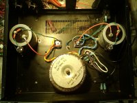
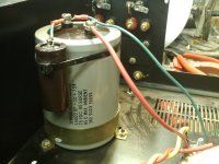
I got as far as having 3/4 of the PS built tonight. I'm going for build type 3 with the IXTH6N50D2. Tx is 650Va, 2 x 50V secondaries and I'm aiming at dual mono-ish. PS caps are 15000uF>>1r>>680uF bypassed with 10uF film. Those big caps are the size of a can of coke. The chassis is from a dead B&K amp. Heatsinks will be a bit undersized I think. I might try mounting the 1R on the base or side of the chassis to spread the heat a bit.
for the output caps I have some Elna 6800uF electrolytics and I might bypass them too.
Pics:
60W = ~70R
100W = ~40R
150W = ~30R
250W = ~20R
500W = ~8R
so from that it seems the sweet spot is 250W bulb. Next thing is trying to find some!!
I got as far as having 3/4 of the PS built tonight. I'm going for build type 3 with the IXTH6N50D2. Tx is 650Va, 2 x 50V secondaries and I'm aiming at dual mono-ish. PS caps are 15000uF>>1r>>680uF bypassed with 10uF film. Those big caps are the size of a can of coke. The chassis is from a dead B&K amp. Heatsinks will be a bit undersized I think. I might try mounting the 1R on the base or side of the chassis to spread the heat a bit.
for the output caps I have some Elna 6800uF electrolytics and I might bypass them too.
Pics:
Attachments
Fran, I bet it will be noisy without another more cap or another resistor in the picture here. I use 15,000uf-1R-60,000 dual rail.
mmm. OK thanks for the heads-up. I'll start scavenging for big caps... if the worst comes to the worst, I can always go back to single supply and then I would have 15000>1R>15000. I would have used the 6800uF Elnas in the power supply, but they are 50V rated and the rails will be above that I think. Could also try bigger resistor too maybe - I think I have some big 5 or 10R power resistors.
What I might do is try it as is, and see what I get. At least that way we'll know for sure.
Fran
What I might do is try it as is, and see what I get. At least that way we'll know for sure.
Fran
- Home
- Amplifiers
- Pass Labs
- Pass "DeLite" Amp from BAF