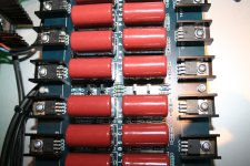
Here is mine, its stil under construction, I used a solid brass bar to share heat equally, ran out of solder wick, see adc chip, a mess, gain devices are harris intersil


Update.
I powered it up today and everything seems to work okay, relays are switching and I see ac when touching inputs, no measurements yet.
I have a question, what current should I expect across the 3.3 ohm resistor? I'm only seeing 65ma,
Question two, the 2k trimmer, how to set it ? Equal gain? Or balance the dc before coupling caps?
Ps tested it with 60 volt
Please ignore my previous post, some reading explained its gain function.
Mail man just brought me this feme rotary switch, it can switch from three balanced sources,
Quality looks outstanding, industrial grade.
I've seen different models for sale, and they are cheap.

Mail man just brought me this feme rotary switch, it can switch from three balanced sources,
Quality looks outstanding, industrial grade.
I've seen different models for sale, and they are cheap.
Hi everyone!
I have som issues with my Clone Aleph P1.7, I have just started the hole thing up, but almost no noice, very very weak!
I am suspect that the problem are something on the PCB (from KK-PCB as I think several of you have knowledge about!?).
I have checked the resistor value, and they are correct, but still, my measurement reading 0V at the resistor as should have 0,65V over the resistor, and also the measure point after T2 and T9, both channel, are 0V measured to ground. Both channel are measured exactly the same... And same low volume level at both channel.
The input read 61.5V both channel. I have separeted power supply, also KK-PCB.
I have Dantimax Input selector and volume control, they are working fine when I bypass the P1.7 PCB.
Therefor I'm pretty sure that it is something wrong with the IRF610/9610 or/either ZTX450/550!? I have already change on one channel without any progress.
Thats I dont counted on?
I have connected the P1.7 KK-PCB according to the instructions.
Any ideas anyone?
Maybe further measure points I chould check?
I'm grateful for any ideas!
Best Regards, Mikael
Hi Zen!
Thanks for reply!
I have put in some pics, just tell me what you want more pics of, if you need more?


Thanks for reply!
I have put in some pics, just tell me what you want more pics of, if you need more?
try posting better resolution schm
say 1200pix
check proper placement of IRF mosfets and BC transistors... often error is swapping their places
say 1200pix
check proper placement of IRF mosfets and BC transistors... often error is swapping their places
Hi Zen! I will try to fix better pics tonight after work, I have check the IRF's and ZTX transistors, but I take your advice and recheck them more accurately.
Hi again! Sorry, no pics today after all, I got home to late from work, but I took my time and checked that all IRF, ZTX and diod's are correct mounted.
I have build a couple of working Aleph 1.2 and a Whammy so I'm not complete beginner, but I'm stuck here.
I'll try to fix better pics, but can take a few days.
At mean time, no further measure point I'll should check?
I have build a couple of working Aleph 1.2 and a Whammy so I'm not complete beginner, but I'm stuck here.
I'll try to fix better pics, but can take a few days.
At mean time, no further measure point I'll should check?
if rails are connected and confirmed as existing on pcb, all we can do is to stare at goats, as soon you post their pics
You've got an awful lot going on in there with the attenuator, input switching, etc. Did you test the preamp board by itself, just running a signal in and looking at the output? Would probably require use of an oscilloscope with no volume control in place.
can you post better resolution schematic?
are all ZTX transistors in proper place, and oriented properly?
it'll be best if you have any of these free (out of pcb), to check pinout with actual measurement - if you have chinese multipractic testing gizmo ....... easiest with that
are all ZTX transistors in proper place, and oriented properly?
it'll be best if you have any of these free (out of pcb), to check pinout with actual measurement - if you have chinese multipractic testing gizmo ....... easiest with that
Thanks for trying to help me guys!
Pars, I've bypassed the attuenator etc, but no sounds att all from P1.7 (sounds at very low volume)
I have also tried the attuenator with bypassed the P1.7 and then it works fine.
Zen, I'm sure the ZTX are pinned the right way and also turned in proper place and orientation. I've rechecked this several times, so I'm little lost.
As I mention before, this is not my first build, and of cours it could be wrong sometimes, and I'm are not a electronic engineer🙂
But then i usually sorted it out. This time I got really stuck. If it only was one channel who was not functional, it would be a lot easier.
I will check the ZTX so they are ok. (Bought them from Mouser, but ZTX550 are not avaliable any more, I noticed).
I will be back, but it can take some time, I have very much to do at work a couple of weeks ahead.
Is your input SE or balanced?
I mean, in which way are you using preamp? In case of SE, you should use jumpers at XLR connectors (or where suitable).
T.
I mean, in which way are you using preamp? In case of SE, you should use jumpers at XLR connectors (or where suitable).
T.
- Home
- Amplifiers
- Pass Labs
- Pass Aleph P 1.7 preamp builders thread