Scott, your AD797 sounded OK. It was just twice the price of something else that sounded as good (although slightly different) Another op amp failed to sound good at all. I hope to try others in future, including some AD parts. IF the AD825 were significantly quieter, I would use it over all others. Thanks Scott, for providing me with these parts in mini-dip form, so many years ago.
I found a small stash that I'm keeping for a while. I think these days FET vs bipolar would be the big difference rather than topology. The schematics are so full of superfluous devices, I don't think they would tell you much because the processes are so fast simple topologies and lots of feedback works.
The most interesting stuff is in our RF amps (useless for audio) -100dB THD @100MHz using low feedback and stage by stage linearization.
Ok, what I want is a single diff pair jfet input, with folded cascode pnp on each output, then one side of the cascode going into a current mirror, the other cascode connecting to the output directly, and the current mirror also connecting to the output. This will give a high impedance (current out) output, that can drive a PARALLELED RC time constant, consisting of a .047uf cap and 1600 ohms (or so) that will constitute the first 75us time constant of the RIAA. Give it a shot, if you will.
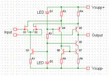
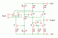
Something like this, John?
Edit: Output compliance will not be great as Q5 is not cascoded.
Also, I worry about the distortion contribution of Q5 and Q8 due to variation of beta etc with collector voltage. For power amps, my simulator tells me this sort of thing is significant. For small signal circuits, maybe not. Then again, maybe it's just in the sim's imagination.
Maybe there are noise issues too ...especially around R3,4,5,6?
Attachments
Last edited:
Looks good. However, driving the output into a 0.047uF cap makes it fairly easy to ignore the extra cascode.
One sugestion. Take out the extra cascode. Insert an NPN bipolar. Base to collector of Q6, emitter to the bases of Q6 and Q7, collector to ground. Resistor from between the bases of Q6, Q7 ( ca.1kOhm to 2kOhm ) to minus PSU. That helper transistor makes the Hfe match between the mirror BJts less critical.
When a transimpedance RIAA is added to the circuit in post 288 the finite output impedance will affect it´s performance. This can be trimmed by making the resistors in the RAA a bit higher then the strict mathematical values that asume an infinite output impedance.
Hi Joachim
How can we compute the finite output impedance of the circuit so we can calc the Riaa resistor´s values ?
How can we compute the finite output impedance of the circuit so we can calc the Riaa resistor´s values ?
Actually is appears at being parallel to the transimpedance resistors. One simple way is to connect a resistor and a cap to ground at the output and measure frequency response. You can then "backcalculate" the output impedance by adjusting the resistor until the desired response is reached. The other ways are simulating or classical mathematics.
I simm'ed the first stage.. get a gain off app 50 dB and quite low distortion...-75 db, nice distribution also.. distortion figures improve when run on higher voltage tried 15 24 and 28 V, but noise may increase... took 7 mA through the fets and 10 mA through the cascode...Nice
Last edited:
Sounds like a good compromise, Miib. The focus here is to pass fast pulses through the input stage, without severely compromising the audio portion of the circuit. This is one of the reasons why I need high slew rate IC's, the higher the better, but even that is not enough.
We debate single ended vs differential but has anyone ever tried a dual triaxial connection on a single ended phono input?
Most expensive (quality) audio cables are Triaxial. That is why the shield is connected to only one end.
I'll try to simm the slevrate....by running a Square through it...
Scott.. never heard of that...triaxial...Do you have a typo schematic..??
Scott.. never heard of that...triaxial...Do you have a typo schematic..??
We debate single ended vs differential but has anyone ever tried a dual triaxial connection on a single ended phono input?
I forget which issue of AX I showed how to do that.
So.. running balanced...with +/- GND..is triaxial..the GND continues through the arm to the cartridge shell.... If you take the GND from the Signal GND and run it through a Ground post it can be done.. the two coils floating...and the GND shielding the signals going to the head amp...
- Status
- Not open for further replies.
- Home
- Source & Line
- Analogue Source
- Parasound JC3 Phono

