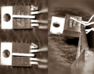
I wish to show a real 2-chip parallel LM1875 point to point done quickly and easily.
Reasons to do it:
The little chip is hi-fi, clear, easy, inexpensive, and it isn't hobbled by the harsh clipping of the spike system (which is absent), so Parallel LM1875's "RMS power" output is a strong competitor to single larger size chip amplifiers. A further difference is the slightly dark voice which is helpful in applying an NFB cap for its advantages to speaker safety, longevity and fun dynamics, yet with the outcome of a level frequency response.
Higher power applications:
This tiny parallel amp can be used for 4 ohm speakers without bridging, or you could add bridging for 8 ohm speakers.
My application:
I, personally, need this clean little high current amplifier in order to interview candidates for bridge adapter. It is a real amplifier. Your input on the electrical circuit(s) is welcomed and desired.
The photo shows small size wire bender pliers (small rounded needle nose pliers) safely bending the pins so that we can attach the power rails.
Attachments
Last edited:
I'm very interested in this parallel design.
Could you please post a build sheet with a sketch diagram?
I have a line on some aluminum extrusions that would accept two of these nicely
for a pretty sweet dual mono compact amplifier.
Thanks
Could you please post a build sheet with a sketch diagram?
I have a line on some aluminum extrusions that would accept two of these nicely
for a pretty sweet dual mono compact amplifier.
Thanks
Yes, this is great. I was stalled out while trying to find the heatsink.
If possible, use the pre-insulated transmitter type extrusion.
It has a very thick black shiny non-conductive coating. Tabor makes most of them.
The really bent teflon frying pan on sale at the dollar store may also work or may need a heat spreader bar added.
After install, just check with the ohmmeter between tab and heatsink to insure no conductivity to electricity--tab is v- rail.
And hey, I've got to find my heatsink before soldering, because it is a rigid assembly and it is also necessary that the bolts like up with the spaces, not the fins. . . because I'm using bolts, not self tapping screws. I just don't have self tapping screws that fit the shoulder washers. 🙂 So, I'm temporarily stuck.
Last edited:
I am a radio technician and as such I have access to strange extrusions for radio parts.
One such radio I work on has aluminum extrusions that are 3/16 thick aluminum rectangle tube approximately 3x4.5x6 with raised ridges similar to heatsink fins on the two narrow edges.
They are coated in some sort of thermal conductive non-electrical conductive black finish that is very handsome.
They are tapped at both ends for 4 M6x5mm screws.
I think it would make a wonderful 2 parallel LM1875 mini monoblock for 4Ω speakers.
If one accepts the design thought that a single 1875 driven to it's maximum capabilities is at it's limit on an 8r0 load, then would it be sensible to use more than an 8ohm as the nominal speaker load for each single chipamp?
If so, then I suspect that a dual could probably drive a 6ohm speaker and a triple could probably drive a 4ohm speaker.
I raise this design issue because the 1875 is stated to have a minimum output current of 3Apk and a typical output current of 4Apk (when output voltage is >10V below supply voltage, this is the loaded supply voltage while delivering that output current). This is further confirmed in the text as an active 4Apk current limiter that operates when Vce is low and is designed to trigger at lower currents when the Vce is higher.
Last edited:
Lets' take a +-30Vdc supply absolute maximum supply that runs at a normal (quiescent) +-27Vdc.
Take an 8r0 load and drive to maximum output.
The expected maximum voltage is ~4V less than the loaded supply rail voltage. Expect that normal +-27Vdc to drop to +-24Vdc when under load. Subtract a further 4V for losses through the chipamp. Maximum sinewave output voltage is ~20Vpk and current is ~2.5Apk. So far output current limit is OK.
Now move to a reactive speaker load where transient current demand can approach 3times the resistive load demand.
For a 4Apk of short term transient demand, expect the supply voltage to not droop as in continuous sinewave testing.
The normal Vsupply stands at +-27Vdc and the 4Apk limit applies when chipamp Vdrop is 10V, we have 17Vpk available at the speaker terminal and 4Apk limited current capability.
The effective impedance is required to be ~4.25ohms. This is only a transient:continuous 4:2.5 ratio of currents, i.e. 1.6times the resistive load current peak.
We are at ~ half the potential peak demand of short term transients of 7.5Apk.
Basically the chipamp can drive an 8r0 load as specified in the datasheet.
It cannot drive an 8ohm severe reactance speaker load when using reasonable near maximum supply and speaker operational conditions.
Substitute 12r0 and 12ohm speaker and you will find that the 1875 comes much closer to being able to drive a higher impedance reactive load. 4:1.67 gives ~2.4times into reactive short term transients. 2.4times for 12ohms is much better than 1.6times for 8ohms
This short design exercise has not yet taken account of the reducing output current limit when Vce of the output devices is higher. National don't specify how that IV limiter operates.
Last edited:
Thank you for the information.
I am at odds with one of the figures. It is that 30. Please don't do that.
The amplifier drives 4 ohm speakers conditionally, and those are not the conditions. Firstly, do not start at +-30vdc. That hinders longevity. Please replace that with +-27.5vdc or less (whether the amplifier is attached or not).
Last edited:
@AndrewT What do you think of "PI filter overdo" (a larger "R" in CRC) as a safety current drop mechanism? And, if that seems wise then I wonder what is the "R" that should be on the schematic?
Apparently, several LM1875 applications need a little bit of added current limiting for safety.
Apparently, several LM1875 applications need a little bit of added current limiting for safety.
Last edited:
I will be running 18v secondaries so even at 4Ω the 1875 should be able to remain nice and safe especially when 2 are in parallel.
I will be looking at building these on a perfboard since my proposed enclosures have a slot at the bottom to accept PCB.
SO, I'm looking at a minimal component count setup for perfboard that I can order from Digikey.
Digikey has a great supply of 1875 and I can get the special size perfboard from them.
Dan + Ein,
put your numbers in and check what to expect for current capability and current demand.
Dan look again, I said Normal quiescent supply voltage of +27Vdc.
You are complaining that is too high and yet suggest +-27.5Vdc !
Can't you read english?
put your numbers in and check what to expect for current capability and current demand.
Dan look again, I said Normal quiescent supply voltage of +27Vdc.
You are complaining that is too high and yet suggest +-27.5Vdc !
Can't you read english?
Dan + Ein,
put your numbers in and check what to expect for current capability and current demand.
Dan look again, I said Normal quiescent supply voltage of +27Vdc.
You are complaining that is too high and yet suggest +-27.5Vdc !
Can't you read english?
You said +-30 abs max. I said +-27.5 abs max.
Running steady at more than approximately +-26 is an amplifier that won't last for a decade, because given a long enough time, there is sure to be a power surge during operation. Meanwhile, back to that question on the R in the CRC for some safety current limiting?
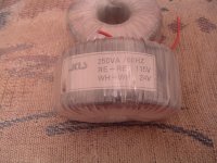
Transformer
For LM1875, the output of these is either too little or too much.
So, here are some possible options. . .
I could write a gigantic answer as to what transformer, smps, capmulti or regulator options we could use, but in constraining the answer down to our 5 minutes per section assembly time goal, plus excellent performance, I have this abridged list for your consideration:
Rectifier
KBPC2504 or KBPC1604 rectifier snubbed as shown in the Mark Houston Synergy amplifier--just look that up. This high quality rectifier has a steady voltage drop that I find more suited, quieter, and safer than the more variable fluctuation of a fast diode marketing gimmick. Although opinions may differ, the high quality KBPC2504, snubbed with inexpensive polyester, meets all of our goals, including low noise performance, lower fluctuations, better thermal management, higher durability, and short assembly time.
Conservative choice transformer
A 15+15VAC 4+ ampere transformer, while a couple of volts low also promotes easier voicing due to lack of overrun condition, lower heat, and promotion of longevity, without the need to fuss or waste time over push for power design. This one meets all of our goals, including 5 minutes or less hookup. It still meets the goals if you slightly unwrap/rewrap a toroid to change it to a 16+16VAC.
Push for Power choice transformer
An 18+18VAC 4+ ampere transformer is what you would use for push for power design with this amplifier, at the possible expense of some longevity. We would be fussing over adding some means of current drop, possibly the retail ribbon cable trick or PI filter overdo, and in either case cannot meet assembly time goal.
However, you can adapt an 18+18VAC toroid transformer with the unwrap/rewrap trick to get 16.7vac+16.7vac or less, and in this case it meets all of the goals.
Linear unregulated power board
For the 15+15VAC to 16.7+16.7VAC choices, a simple pack of 5 or so paralleled 2,200uF 35v inexpensive caps per each rail (a 10 pack for a split rail board) plugged into a scrap of copperless (no pads) Phenolic board.
For the 18+18VAC push for power option, 4,700uF 50v at the rectifier, 10w resistor and 10,000uF 35v, per each rail in a standard CRC design. It can also be put together on a scrap of copperless phenolic perfboard in just a few minutes.
Transformer amperage
The linear unregulated supply has an weird transformer requirement. If you are using a speaker with your amplifier then your transformer needs to be at least 4 amperes, no matter if dual mono or stereo. Just like woofers and bells, you need a big one if you want bass. Of course a 6 ampere transformer is fine too, because like the 4 ampere transformer, it is also big enough.
Theory: The transformer plus rectifier of the linear unregulated supply are the same thing as fastest possible battery charger, whereby the higher amperage models charge the caps faster and those caps must stay always brim full during playback if you want good performance.
Maths: VA figures 15+15VAC*4a=120va is volts times amperes. Likewise 4a with 18+18vac transformer = 144va, which is 4 times (18+18) = 144VA.
Using a minimum VA figure is not required, you can use a higher amperage model if you wish.
SMPS Alternative:
It is also possible to use a pair of adjustable 24vdc SMPS; however, SMPS, being switchmode technology spends half of its time asleep. Exactly like the computer with the 200 watt demand needing a 430 watt power supply, an SMPS always needs "double-rated" meaning you buy at least twice as much amperage as you need. If there is availability of a pair of sturdy 15a or better SMPS, they are quite useful as amplifier power sources. It takes two units to make a split rail power source for a stereo amplifier, and they must be isolated. Further documentation is at Decibel Dungeon, just look that up.
FAKE (generic) LM1875
Transformer 12.5+12.5 (the common 24vct industrial center tap)
Flyback diodes as seen in the TDA2030 datasheet
About a step smaller capacitance at the chip than for LM1875
Maximum feedback resistor is 68k for fake, 115k for authentic
Generic LM1875 uses Datasheet for TDA2030
Likewise, with such accommodation a real TDA2030/2040/2050 is usable.
Dual mono
Dual mono refers to 1 pair of monophonic, aka monobloc amplifiers put into a single enclosure, and wired exactly like monoblocs, the dual mono amplifier gives a somewhat wider presentation for double the power supply expense of a stereo amplifier.
Conversely, a stereo amplifier is two amplifiers in a single enclosure with only one power supply, and this arrangement is a bit more normal and costs less.
More information
Decibel Dungeon DIY hi-fi index.
There is much more information than this, plus helpful examples at Decibel Dungeon.
Save your 2 of 24vac transformers for using as a 24+24 transformer with stereo TDA7294 or stereo LM3886 MyRef.Could I use these transformers or do I need a single with dual secondaries.
For LM1875, the output of these is either too little or too much.
So, here are some possible options. . .
I could write a gigantic answer as to what transformer, smps, capmulti or regulator options we could use, but in constraining the answer down to our 5 minutes per section assembly time goal, plus excellent performance, I have this abridged list for your consideration:
Rectifier
KBPC2504 or KBPC1604 rectifier snubbed as shown in the Mark Houston Synergy amplifier--just look that up. This high quality rectifier has a steady voltage drop that I find more suited, quieter, and safer than the more variable fluctuation of a fast diode marketing gimmick. Although opinions may differ, the high quality KBPC2504, snubbed with inexpensive polyester, meets all of our goals, including low noise performance, lower fluctuations, better thermal management, higher durability, and short assembly time.
Conservative choice transformer
A 15+15VAC 4+ ampere transformer, while a couple of volts low also promotes easier voicing due to lack of overrun condition, lower heat, and promotion of longevity, without the need to fuss or waste time over push for power design. This one meets all of our goals, including 5 minutes or less hookup. It still meets the goals if you slightly unwrap/rewrap a toroid to change it to a 16+16VAC.
Push for Power choice transformer
An 18+18VAC 4+ ampere transformer is what you would use for push for power design with this amplifier, at the possible expense of some longevity. We would be fussing over adding some means of current drop, possibly the retail ribbon cable trick or PI filter overdo, and in either case cannot meet assembly time goal.
However, you can adapt an 18+18VAC toroid transformer with the unwrap/rewrap trick to get 16.7vac+16.7vac or less, and in this case it meets all of the goals.
Linear unregulated power board
For the 15+15VAC to 16.7+16.7VAC choices, a simple pack of 5 or so paralleled 2,200uF 35v inexpensive caps per each rail (a 10 pack for a split rail board) plugged into a scrap of copperless (no pads) Phenolic board.
For the 18+18VAC push for power option, 4,700uF 50v at the rectifier, 10w resistor and 10,000uF 35v, per each rail in a standard CRC design. It can also be put together on a scrap of copperless phenolic perfboard in just a few minutes.
Transformer amperage
The linear unregulated supply has an weird transformer requirement. If you are using a speaker with your amplifier then your transformer needs to be at least 4 amperes, no matter if dual mono or stereo. Just like woofers and bells, you need a big one if you want bass. Of course a 6 ampere transformer is fine too, because like the 4 ampere transformer, it is also big enough.
Theory: The transformer plus rectifier of the linear unregulated supply are the same thing as fastest possible battery charger, whereby the higher amperage models charge the caps faster and those caps must stay always brim full during playback if you want good performance.
Maths: VA figures 15+15VAC*4a=120va is volts times amperes. Likewise 4a with 18+18vac transformer = 144va, which is 4 times (18+18) = 144VA.
Using a minimum VA figure is not required, you can use a higher amperage model if you wish.
SMPS Alternative:
It is also possible to use a pair of adjustable 24vdc SMPS; however, SMPS, being switchmode technology spends half of its time asleep. Exactly like the computer with the 200 watt demand needing a 430 watt power supply, an SMPS always needs "double-rated" meaning you buy at least twice as much amperage as you need. If there is availability of a pair of sturdy 15a or better SMPS, they are quite useful as amplifier power sources. It takes two units to make a split rail power source for a stereo amplifier, and they must be isolated. Further documentation is at Decibel Dungeon, just look that up.
FAKE (generic) LM1875
Transformer 12.5+12.5 (the common 24vct industrial center tap)
Flyback diodes as seen in the TDA2030 datasheet
About a step smaller capacitance at the chip than for LM1875
Maximum feedback resistor is 68k for fake, 115k for authentic
Generic LM1875 uses Datasheet for TDA2030
Likewise, with such accommodation a real TDA2030/2040/2050 is usable.
Dual mono
Dual mono refers to 1 pair of monophonic, aka monobloc amplifiers put into a single enclosure, and wired exactly like monoblocs, the dual mono amplifier gives a somewhat wider presentation for double the power supply expense of a stereo amplifier.
Conversely, a stereo amplifier is two amplifiers in a single enclosure with only one power supply, and this arrangement is a bit more normal and costs less.
More information
Decibel Dungeon DIY hi-fi index.
There is much more information than this, plus helpful examples at Decibel Dungeon.
Last edited:
Designs / Schematics
http://www.diyaudio.com/forums/chip-amps/120616-lm1875-pcb-use-4.html#post1696460
All over that thread is LM1875 optimizations, discussions, schematics and opinions.
It is my intention to show an assembly method. You can use any schematic you like. Some of the charms of the LM1875 is that you can build your own thing, with quick success, high resolution, and minimal cost.
For parallel, add 0.22 ohm 3W or better resistors series with the speaker output of each chip. This small resistor loss is common to most parallel amplifiers so that they don't fight.
Resistor matching is necessary for parallel amplifiers.
Measure all resistors with digital ohmmeter to be sure that:
all feedback resistors are identical
all feedback-shunt resistors are identical
all stopper resistors are identical
all input load resistors are identical
so where is the schematics?
http://www.diyaudio.com/forums/chip-amps/120616-lm1875-pcb-use-4.html#post1696460
All over that thread is LM1875 optimizations, discussions, schematics and opinions.
It is my intention to show an assembly method. You can use any schematic you like. Some of the charms of the LM1875 is that you can build your own thing, with quick success, high resolution, and minimal cost.
For parallel, add 0.22 ohm 3W or better resistors series with the speaker output of each chip. This small resistor loss is common to most parallel amplifiers so that they don't fight.
Resistor matching is necessary for parallel amplifiers.
Measure all resistors with digital ohmmeter to be sure that:
all feedback resistors are identical
all feedback-shunt resistors are identical
all stopper resistors are identical
all input load resistors are identical
Last edited:
NFB Cap for durability and for fun
I will promote using an NFB cap and show how to do a nice job of it. An NFB cap gives you speaker safety, a more durable amplifier, a longer lasting amplifier, and MUCH MORE FUN DYNAMICS.
One aspect that nobody talks about is that NFB caps are much easier to apply and more successful for audio if using a design that is supposed to be AC coupled.
These all have generally higher resistor values for gain setting, such as:
(feedback resistor / feedback shunt resistor with NFB cap)
68k/2.7k with 220uF (general purpose)
100k/3.3k with 100uF//22uF or 150uF (super clean treble)
100k/2.7k with 220uF (high gain)
56k/2.2k with 220uF//22uF (television amplifier)
47k/2.2k with 220uF//22uF
47k/2.7k with 220uF (low gain)
47k/1.5k with 330uF//22uF
*in the above cases you can use larger cap values as it only matters that they are big enough and also clear. You can also use parallel capacitors, such as big electrolytic with small electrolytic, or big electrolytic with small polyester, or any combination thereof as long as it is big enough and also clear.
Selecting an NFB cap or Input cap:
Capacitor quality varies regardless of price, but the solution isn't difficult.
Take five likely candidates of the correct value, try all five and keep the nicest. Also attempt adding very small value (10nF?) polyester for more entertaining treble. I'm not so sure about just five minutes with that method but it is quick inexpensive and higher fidelity. Price doesn't equate to performance with capacitors. Enjoy your powerful clean dynamics.
EDIT:
Credit to AndrewT for fixing MY amplifier by up-sizing my NFB cap until the amplifier is capable of clean extra low bass. That was a great learning experience. Thank you.
Last edited:
The resistor values for using with an output cap or a 3rd party speaker protector are:
27k feedback, 820R feedback-shunt, 10k input load, 470R stopper, 4.7uF//10nF input cap, 0.22R output ballast.
Check for DC offset individually. That version is neither as durable nor as dynamic as amplifiers with an NFB cap. I'm not using that version.
27k feedback, 820R feedback-shunt, 10k input load, 470R stopper, 4.7uF//10nF input cap, 0.22R output ballast.
Check for DC offset individually. That version is neither as durable nor as dynamic as amplifiers with an NFB cap. I'm not using that version.
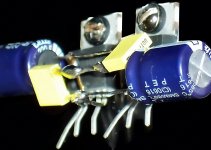
Photo of the rails
Compare to the photo in post #1
This is a minimal parts and minimal effort way to put rails on a miniature parallel amplifier. A circuit board alternative to this would be to simply put the power caps midpoint between the two chips.
Possible values for this location:
100nF or 47nF for the small caps.
220uF or 330uF or 470uF for the 35v large caps.
330uF is a standard value for this chip--larger is more laid back, smaller is brighter.
Attachments
That solution looks great.
It is a little hard to see what goes where though.
A little more info would be greatly appreciated.
Thanks
It is a little hard to see what goes where though.
A little more info would be greatly appreciated.
Thanks
Thanks for the reply Daniel. The transformers are actually for your LM3886 kit that I plan on building soon. I've built your 1875 amp and thought the parallel implimentation would be something that would use your PCBs.
It's interesting that you mention using an array of smaller caps for the power-supply. I was trying to figure out a way to do that with my 1875 amp yesterday!
Got a good link for building your LM3886 kit?
It's interesting that you mention using an array of smaller caps for the power-supply. I was trying to figure out a way to do that with my 1875 amp yesterday!
Got a good link for building your LM3886 kit?
- Status
- Not open for further replies.
- Home
- Amplifiers
- Chip Amps
- Parallel LM1875, 2 chips per channel, in 5 minutes ea? Can bridge if 8 ohm speakers.