Ok Guys
Actually, I have a few different kinds of HV wire...But yeah, no 600V crap on the HV. And the ptfe, and ftpe, on the rest of it because I like how it doesn't melt and is resistant to, well, everything.
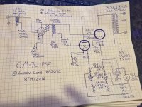
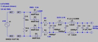
Thanks for all the comments...keep it coming..Here's the amp minus my few mistakes and the things I forgot to label. And here's the power supplies, minus the B+ for the D3a because I'm still waiting on those transfos, and the Filament supplies for the GM70, but they are simple, 10,000u, .025H, 10,000u.
Anyway like I said, keep the comments and constructive criticism coming. Thanks guys.
Actually, I have a few different kinds of HV wire...But yeah, no 600V crap on the HV. And the ptfe, and ftpe, on the rest of it because I like how it doesn't melt and is resistant to, well, everything.
Thanks for all the comments...keep it coming..Here's the amp minus my few mistakes and the things I forgot to label. And here's the power supplies, minus the B+ for the D3a because I'm still waiting on those transfos, and the Filament supplies for the GM70, but they are simple, 10,000u, .025H, 10,000u.
Anyway like I said, keep the comments and constructive criticism coming. Thanks guys.
Attachments

Actually, I have a few different kinds of HV wire...But yeah, no 600V crap on the HV. And the ptfe, and ftpe, on the rest of it because I like how it doesn't melt and is resistant to, well, everything.
Thanks for all the comments...keep it coming..Here's the amp minus my few mistakes and the things I forgot to label. And here's the power supplies, minus the B+ for the D3a because I'm still waiting on those transfos, and the Filament supplies for the GM70, but they are simple, 10,000u, .025H, 10,000u.
Anyway like I said, keep the comments and constructive criticism coming. Thanks guys.
I would consider doing the bias circuit differently.. You're at the mercy of the wiper on the pot.
Here's a thread where I asked for some assistance with my bias supply.
http://www.diyaudio.com/forums/tubes-valves/283101-bias-circuit-fixed-bias.html
You're right, I need to connect those on the schematic. One of the reasons I chose the voltage range on the bias's was for that reason, that if something goes wrong I am just at the highest voltage. But doesn't do much good if it's not hooked up like that. Will do, I'm sure I'll be posting another more final schematic, but it's close enough at this point for stuff like this. All those "umm, were you going to..,,".
Thanks again,
Oh and I forgot to respond yesterday on the input transformer...,yeah I agree, too much of anything...but I'm going to try for sure. I'd like to be able to forgo the bypass cap on the cathode of th D3a...and it wouldn't work with just a resistor the plate R would be way too high...so, we'll see how it tests out and sounds,
Ok Thanks again
Loren
KB2WYL
Hi all. So been talking with Rod about the filament regulators. Just in case anyone doesn't already know, Rod stands behind his products in a way I only wish more manufacturers did. He has been very kind putting up with my questions.
I have not done Choke Input on a heater supply before, and it turns out that these Triad VPS-36-4800 that I have here are perfect for the job. I did a test run with .025H, .47 ohm old stancor chokes. Using them, into then a CRC of 10k, .82ohm, 10k, and loading the whole thing with 6.6 ohms (GM70 filament) I get 25v, perfect for the regulator board. I'll post schematics later hopefully if I have time.
But there is a bit of hum from the choke, and I don't want that to couple electrically or physically to anything else. Remember this is all on a monoblock.
So I figured I'd see, who else here has done choke input DHT? Rod suggested a filter and I'm sure going to try it, any one else have a scheme that worked for them?
Thanks all,
Loren
KB2WYL
I did choke input colemans on my GM70.
Used his published schematic along with a hammond transformer as specified.
I'll check Spice, I might have a model
Used his published schematic along with a hammond transformer as specified.
I'll check Spice, I might have a model
Hi Loren,
I regularly -for years ago- use r-C-L-C-CMC-C type raw DC PSUs before Rod's regulators - over 2..3A - (or r-C-CMC-C below it), because I notoriously hate filament hum.
I tried choke loaded one, but the total cost was a little high (I only have appropriate core from amorphous material), and the result wasn't so much better.
Sample: one my 801a PSE filament PSU schematic and raw PSUs on experimental state (in middle 801a PSE PSU) .
Attachments
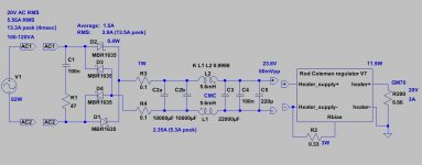
Thank You. I tried real quick before I went to work with an rCLCRC and it worked great. This is dissapating a little more heat than I would choose if I was starting from scratch, but certainly nothing I can't deal with. The transfo is 36v secondary and arrangement was .1r, 30uf, .025H, 10kuf, .47r, and 10kuf. This gives me 25.2V, and I'm sure the ripple is very low. I'll sim it later but this arrangement leaves me needing nothing else than a few chassis mount .47 resistors...
For me it is just wanting to try the choke input, as well as having this stuff on hand...with an 18V parallel or 36V series transformer this seems a good way to come out enough above 20V for the regulators, so the current reduction in the transformer and possible benefits of noise reduction are just added benefits for me.
Thanks again, especially for the pics I enjoy getting to see others' work.
Loren
KB2WYL
I did choke input colemans on my GM70.
Used his published schematic along with a hammond transformer as specified.
I'll check Spice, I might have a model
Yes please
I'd love that. I have 2 of the Hammonds as well, but I didn't think there was any chance of using them choke input? 10V parallel, or 20VCT, seems like the only way to come up with north of 20VDC is by using the secondary series, and then using a FWB. Am I missing something?
I did choke input colemans on my GM70.
Used his published schematic along with a hammond transformer as specified.
I'll check Spice, I might have a model
I'd love that. I have 2 of the Hammonds as well, but I didn't think there was any chance of using them choke input? 10V parallel, or 20VCT, seems like the only way to come up with north of 20VDC is by using the secondary series, and then using a FWB. Am I missing something?
Those polarities look somewhat odd.Perhaps better like this ?
Direction of the arrows not conventional(+ to -) but electron flow (from - to +).
Mona
Hi Mona,
With my Regulators, you can connect either FILAMENT + or FILAMENT - as the anode return ("cathode" connexion).
Naturally, the bias must be adjusted to get the same anode current.
But many constructors have told me that the + side grounded sounds best, and I think it does too. I can't see any convincing reason why it is like this, so I can only say that whoever is interested, must experiment!
Hi all. So been talking with Rod about the filament regulators. Just in case anyone doesn't already know, Rod stands behind his products in a way I only wish more manufacturers did. He has been very kind putting up with my questions.
I have not done Choke Input on a heater supply before, and it turns out that these Triad VPS-36-4800 that I have here are perfect for the job. I did a test run with .025H, .47 ohm old stancor chokes. Using them, into then a CRC of 10k, .82ohm, 10k, and loading the whole thing with 6.6 ohms (GM70 filament) I get 25v, perfect for the regulator board. I'll post schematics later hopefully if I have time.
But there is a bit of hum from the choke, and I don't want that to couple electrically or physically to anything else. Remember this is all on a monoblock.
So I figured I'd see, who else here has done choke input DHT? Rod suggested a filter and I'm sure going to try it, any one else have a scheme that worked for them?
Thanks all,
Loren
KB2WYL
Thank you, Loren!
Yes, I like choke-input raw dc supplies, especially for Transmitter tubes. The reduced current-peaks makes a notable reduction is wasted power in the transformer, rectifier and caps - lower stress all around.
And nearby DACs and MC cartridge stages will be glad of the lower EM, and mains-conducted emissions as well.
Rod,
What's your opinion on using lab grade regulated linear power supply instead of the regular DC filtered raw supply?
Rod,
What's your opinion on using lab grade regulated linear power supply instead of the regular DC filtered raw supply?
Hi James,
Yes, you can use a lab regulated supply. The performance will probably be the same as with a normal CRC supply, since the Regulator will achieve microampere level ripple-current using the recommended raw dc, given in the manual.
Also, beware that some lab supplies don't like a constant-current load; probably worth checking that it does not make the lab supply unstable.
But, it might be worth it, as you can experiment and compare different tubes: the regulators only need a resistor change, to switch from GM-70 (3A) to SV572 (4A) say. Or you can switch between 211/845 (3.25A) and GM-70 (3.0A) with no changes beyond adjusting the supply input voltage - since the current is fine-adjusted using the on-board trimmer.
Thanks Rod! I will try and experiment it a bit with the 845 tubes.
What changes are required for the 845 (3.25A) regulator to use with 833 (10A@10V)? Can the V4 board accommodate such changes? I have a couple of Brand New Extras I like to use with the 833 filaments.
Thanks!
Hi James,
There are standard configurations of my regulator for the RCA 813 (10V 5A) or the Eimac 100TH, 100TL, 75TL etc (5V 6.3A), and with the right resistors available, you can switch between them.
For the 833C, the limitation is mostly the startup power pulse. The cold-resistance of the filament is almost zero ohms, and the filament voltage near to zero at switch-ON, even at 10A! So the current-control power transistor must manage this power, until the filament warms up.
(near to) 100W is too much to reliably manage, so the solution for 833C is to use two 5A regulators in parallel. This works perfectly reliably, because there is no voltage-feedback loop on the regulators, and they do not argue.
Magz used this arrangement in the "Mid-Life Crisis" - an excellent design overall, well worth a look for scoping 833C work:
http://www.diyaudio.com/forums/tubes-valves/232484-midlife-crisis-my-833c-amp-build.html
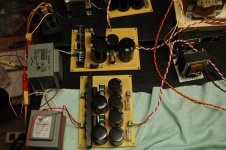
Just a quick note before I retire for the night. Got the main bias supply boards both built. Found a source (onlinecomponents.com) for cheap triad 10H, 90ma, 256DCR chokes, 11$ each. Luckily I had two 5H 115DCR in the shop to test boards with. Slightly different resistor load values then the schematic, but i'm building this thing board by board so as to test everything first, one board at a time. I want to be able to have it all ready, then do final chassis layout, so that I can finish the chassis (powder coat?) before installation. Voltage is 97-118 now, and the final installment will have a 3k instead of 2k 10 turn so probably more like 90-125. Plenty of wiggle room.
How do you guys do chassis? Build it, test, tear down and finish? Or do you try to breadboard as much as possible and have chassis finish coated before install?
I'll post final schematics once I work out all but HV board....I'm not messing with that until secure in chassis, and because +- 100V can be taken care of with cap changes anyhow.
Thanks all,
Loren
KB2WYL
Prototype one channel on MDF (no alligator clip leads on 800V-1000V B+). In fact, I am reluctant to put any clip or hook lead on anything over 300V.
Everything is temporarily hardwired and HV B+ are wired to the terminal strip mounted on the MDF. May be I am crazy but I won't be able to enjoy the amp if I hurt or kill myself.
Then, I transfer everything to the chassis once it's proven on the MDF build.
Everything is temporarily hardwired and HV B+ are wired to the terminal strip mounted on the MDF. May be I am crazy but I won't be able to enjoy the amp if I hurt or kill myself.
Then, I transfer everything to the chassis once it's proven on the MDF build.
That's about what I was thinking
But I was going to mount power transformers in Chassis with just a couple nuts on each. Just to have them sitting in.
The way I figure it, no matter what, I NEED power transformers. So I was going to just set these in chassis. Plus, then I can see how and if they play with each other as far as electromagnetics, since these are "all on one chassis" monoblocks.
Then, once theyre in place, I'll feel a bit safer about hooking up power. All HV stuff either soldered, or terminal'd. All of my ps boards, my interstage transformers, bias boards, etc can and will sit on a piece of some sort of plywood (yeah MDF is nice, easy to screw to)...
I'm changing up values here and there of course from the schematic as I go, PSUD is great but nothing beats real world testing to SEE where voltage is at. Tonight got started on the bias boards for the D3A, so as it sits those are started, gm-70 bias boards are done, and all HV PS boards are done...
Time time time.....Thanks Megasat,
Loren
KB2WYL
Hey guys. Quick question, for those of you running GM-70s between 1, 1.1Kv, what are your Negative Bias's? I just finished the second bias supplies, for the D3as...simplified a bit from the schematic I had posted, and after figuring out un-labeled Mundorf 4-poles...So theyre good, from -2.5 to zero with a 10 turn Bourns...The GM-70 bias boards are sitting from -120 to -97, and with the wiper and top of pot connected even if wiper breaks they still see -120, but I'm thinking I'm going to change it a bit more to be more like -125 to -110 because my calculations show an operating point of -118 and 78ma (6.6K Load).
Thanks guys,
Loren
KB2WYL
Thanks guys,
Loren
KB2WYL
- Status
- Not open for further replies.
- Home
- Amplifiers
- Tubes / Valves
- Parallel GM70 Amp