Thanks Kevin
Let me get this schematic up. The cap coupling I'm still open to. The I rush current won't be an issue as I am going to have the filaments always on standby (barely glowing) as I have seen work for a lot of designs...also leads to longer tube life (well ok maybe not longer than with Rod's boards), but It's not a hard workaround to add the boards. You'll see I just posted asking about the heatsinking and the FWB...
As far as in the main PS...caps are all Epcos Film. 1300v and 27uf paralleled. Sims of this design show a lot of ripple on the first 5uf of course so it is 2 in series with balancing resistors (high V and W). After that and first choke (chokes are rated for this voltage) there isn't too much ripple and second cap shpuldnt ever see more than 1090V. Third cap even less the full 1070V of the supply. In any case, I thought about the negative leg choking too but again having the chokes already...it's just like the output transformers which yes are 3k-6k (depending if you load the 8 with 8 or the 4 with 8 on secondary) and are rated 200ma continuous, 400ma peak, and 100W....they are ridiculous...
So...
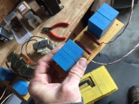
I'm drawing this thing out to post, and one of the last things I had to do was sim these bias supplies that I had...Well, I wanted them to be bias supplies. Got a handfull of them a while back, secondaries are 4 55v windings. theyre small, probably 100va or so...Thought i'd use them for bias supplies, why not, give the bias supply it's own transformer....But....
problem here is that the winding resistance is very high. Primary around 250 ohms and secondaries all in series about 750ohms....give impedance around 1.3k....so when I do the sim I am having to use small capacitance values (100uf, resistor, 100uf, or less) to get it up to power in less than 8 seconds....
This is just trying to use parts that i have on hand, and I figured why not, doesn't hurt to have extra capacitance/filtration in the bias supply. I don't have on hand anything less than 360uf in the electrolytic/200-500v range, so either I need a different transformer or some different caps....suggestions? I wanted to do the bias nicely and filtered, not some old amp half wave trick...
Loren
KB2WYL
In my 813 and GK-71 prototypes I use SMPSes to power filaments. Amps are stereo, both filaments are paralleled. 36 Ohm 8W resistors are between floating ends of the PS, grounded in the middle. Both are shunted by 10,000 uF caps. However, it adds kind of common for both channels "semi-automatic" bias, but it's fine.
I guess I could simplify that...
Does it matter if the Bias supply has a high impedance? I thought actually it might be a good thing...just need to take into consideration the time it takes to come up in the startup scheme...
Loren
KB2WYL
Does it matter if the Bias supply has a high impedance? I thought actually it might be a good thing...just need to take into consideration the time it takes to come up in the startup scheme...
Loren
KB2WYL
when I SIM
it in PSUD, with exact measured values, I get 1.532K. What I'm looking at is that, then 340uf, then a 16H choke with a DCR of 2.4k, then 410uf...This gives me a VERY clean and quiet suply, which of course I like, but rise time is Just Over 10 seconds....Actually, I was thinking this is not too bad. As long as that 1.532k isn't an issue...
Loren
KB2WYL
One down....
Ok I figured out the rectifiers and the heater...so that's done...But this Bias supply (and possibly D3A supply) still has me?
I know that having a high impedance gets me a longer up time to voltage. and that usually a lower impedance is desirable for recovery.
But in the case of the negative bias supply, and i suppose also the D3a anode supply, there could be so much capacitance that once the supplies get up to speed they should be rock solid. Usually this isn't done due to cost and size, but since I have these transformers, and since both supplies only need to be 200V or so...
I tried hooking up these transformers in reverse. 120 to one of the 55V taps and the 110 tap as my secondary. That yields me a lower impedance of 799 ohms on the secondary, according to PSUD (and I must be close predicted values are exactly what I'm getting in testing.
So, is 799 too high of an impedance for a.)negative bias, and/or b.) plate supply, when I have 1200uf of capaitance? It has ripple on the order of a couple millivolts, and it seems to me as long as they are both getting turned on before the Plate supply for GM-70 that it really would be fine?
Thanks all,
Loren
KB2WYL
I use stacked 450V 220uF 20% 105C 5000 hour Panasonic electrolytics stacked 3 in series with voltage equalizing resistors. The current equalizing resistors are 120K 5% 3W. The previous set had 171K resistors across them, and over a period of 5 years I had a cap failure - when I investigated I had 2 open equalizing resistors, and 1 cap had failed (close to venting) and 10 others showed signs of distress. I now use resistors rated at 750V with a high pulse rating and 3W rated dissipation. Unfortunately I am not sure how long these will live. The supply voltage is approximately 1025V but varies several % based on line voltage variations.
How about using these bad boys instead?.. A little pricey, but I mean in an amp like this you're already dropping some big bucks.
PESG5100ALV - Solen Electronique - World leading producer of high-end crossover components
I've used them before, and indeed they are good, unfortunately I did not have the required space available. The stacked electrolytics occupy less space than a single one of those cans and provide about 25% more capacitance per string, and cost a great deal less.
Mine actually weren't that expensive to build originally, maybe $2K for the pair, the subsequent upgrades once I proved the design worked at a basic level have taken it more towards the unaffordium end of the range.. lol
Mine actually weren't that expensive to build originally, maybe $2K for the pair, the subsequent upgrades once I proved the design worked at a basic level have taken it more towards the unaffordium end of the range.. lol
<snip> rise time is Just Over 10 seconds....<snip>
Loren
KB2WYL
With such a slow rise time you will have to delay B+ until the bias is fully up, since you are using tube rectification as long as the rectifiers are indirectly heated you are probably fine.
I'm using interstage transformers and fixed bias, the bias supply is not particularly low resistance once the bias voltage has been fed through the resistor divider string and pot - in my case probably around 2K or so. (Would have to check and calculate) My time constants are such that the bias comes up in a few seconds, just quick enough as compared to the filaments heating up and plate current starting to flow. No preheat or sequenced supplies other than the deliberate minimization of the bias supply time constant. No tube failures either in 5 years.
The GM70 filaments are just tungsten as far as I know and should be OK from the standpoint of poisoning with some sort of low level preheat, but I think you are talking pretty significant power draw and I don't know whether leaving them on all the time might result in a much shorter overall operating life.
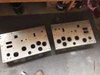
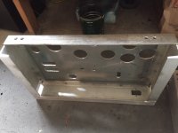
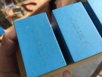
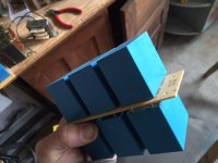
Still working on the Schematic. A lot of work came up past day, so been away from shop. But I did get some work done. I agree with Kevin, those caps are nice, but these Epcos are far, far cheaper, almost as high voltage rating (plenty high enough) and take up far less space. I like them even more than stacked electrolytics because they last longer than even high hour lytics, and if you stack them far longer. Also ESR is very low, and they are self healing. The pics are the chassis which i finally finished except for holes to mount everything underneath (but that has to wait for final schematic), and the board for input cap (5uf x 2, in series with 5ufx2 =10uf series 10uf, = 5uf...with balancing R's. Second cap will be one epcos, same, 27uf 1300v (it sees 1090v with only 20v ripple), and then next pics are the final hv cap bank which is 6 paralleled for 135uf.
As I go through the final planning stages I'm finding a few other things I don't have on hand as well as a couple more questions.
a.) I can use the transformers I have for b+ and bias but if someone has some matching small VA transformers in the 170-400VAC range i'd be interested for sure.
b.) I still need to make a final decision on the coupling. Kevin you especially, what were your impressions IT vs. Cap coupling? I think I have an idea for "matching" tubes in circuit either way (Gm), but the cap coupling would allow me more flexibility with bias matching. I really wanted to try the IT coupling. But I'm seeing more and more of reports as I research, where peoples favorite sound settled on in amps like these (SE transmitting) was with plate choke and cap couple...I have both on hand and some really nice teflon russian coupling caps...
The Lundahls (ll2756) are quoted at 70H at 25ma, and I'll be running about 20ma and also a lesser load than the test sheet (~2k vs 3.5k)...
Opinions?
thanks all,
Loren
KB2WYL
Attachments
How funny right as I was already writing....but still would like your opinion on sound. I think you know I'm not looking for "better" or "airy and clear" just which one you preferred. I really am leaning towards just staying IT, especially at first to try out this Gm balance scheme.
As far as the transformers and rise time....Yeah it took me a while yesterday to work it all out but I have them designed for the b+ and bias and they're working out just fine. Of course yes I will have to work it in so that HV is delayed at least 10 seconds, which will give me an actual delay of at least 16 sec. While the 6CJ3's come up. Not too big of a deal, but this is why I will keep my eyes out for 4 small transformers. I searched a little last night but they're a pain to find, single secondary low VA, anything from 160-400 vac...(I already have heater supplies for the 6CJ3's and the D3a, one for each (6cj3's in series)).
As for the heaters....Definitely don't want them on permanently, if not just from a cost perspective...but...other reports of designs where this has been tried found the tubes lasting longer than on/off, for daily listening. These amps will be getting if not daily then almost daily use, and it makes sense that the inrush current to a cold filament is what ultimately destroys them. I suppose though since I took the step and am ordering boards from Rod, doing it the right way from the start, that this isn't an issue as it is in just a passive supply so...
I guess what it's going to come down to is finding these transformers or not as far as the delay. But either way, sure doesn't hurt to make sure that there is bias, tubes are heated, before firing up HV. Slow start boards are cheap, and after they fire at decided time the 6CJ3's give the soft start.
Thanks,
Loren
KB2WYL
I much prefer IT to choke and cap coupling, but I am using amorphous core 1:1 bifilar wound interstages in my amps.
I've never had a filament failure, the tubes simply cease to sound good around the 1100 - 1200 hour mark and I replace. Emission drops pretty rapidly somewhere past the 1000 hours, I've noted in some cases 30% shift downwards in plate current near the end of life. (It's very stable until very late in the life curve and gets adjusted once of twice over the life of the tubes where only small changes are noted.)
I've never had a filament failure, the tubes simply cease to sound good around the 1100 - 1200 hour mark and I replace. Emission drops pretty rapidly somewhere past the 1000 hours, I've noted in some cases 30% shift downwards in plate current near the end of life. (It's very stable until very late in the life curve and gets adjusted once of twice over the life of the tubes where only small changes are noted.)
Go IT, I went to choke and switched back to IT
Also, try using an arduino to delay the voltage. You can also use it as a safety device
Also, try using an arduino to delay the voltage. You can also use it as a safety device
Thanks. I am going IT. I'm drawing up the final (ha, well you all know what I mean) schematic right now. I'll post tonight. I messed around with the Power supplies a little bit and got the up time down quite a bit...some high henry low DCR (well, for what it is at least, 8H 200 ohm) chokes really help out. Ripple for the D3a and Bias (which incidentally will both be the same exact supply parts wise) is 1mv. Rise time to 95% voltage is 3.5 seconds. Not bad.
Thanks all,
Loren KB2WYL
Thanks all,
Loren KB2WYL
Ok...
Alright all. Couldn't get it all done, just got too tired...been a long few days. But I'm almost there with the PS. Question: For the Bias supply, seeing as though I'm staying away from A2, how low can i go on the ma? I have it sim'd at 30ma, and that gives me Lcrit of 7.6H, perfect for these 8H chokes....and i think 30ma is as low as i want to go anyhow, esp. on a bias supply only needing around 120v anyhow...just a sanity check...
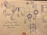
So here's the main schematic. Fixed bias on the D3a through an input transformer. Rod's scheme to balance Gm a little, and my idea to vary said scheme on the GM-70 cathodes. Bias meter onthe D3a, and switchable in/out circuit meter on 1 ohm current sense resistors on the plate of the GM's...
Sanity check #2, let me know what you guys think. More to come, hopefully tomorrow evening,
Thanks again,
Loren, KB2WYL
Alright all. Couldn't get it all done, just got too tired...been a long few days. But I'm almost there with the PS. Question: For the Bias supply, seeing as though I'm staying away from A2, how low can i go on the ma? I have it sim'd at 30ma, and that gives me Lcrit of 7.6H, perfect for these 8H chokes....and i think 30ma is as low as i want to go anyhow, esp. on a bias supply only needing around 120v anyhow...just a sanity check...
So here's the main schematic. Fixed bias on the D3a through an input transformer. Rod's scheme to balance Gm a little, and my idea to vary said scheme on the GM-70 cathodes. Bias meter onthe D3a, and switchable in/out circuit meter on 1 ohm current sense resistors on the plate of the GM's...
Sanity check #2, let me know what you guys think. More to come, hopefully tomorrow evening,
Thanks again,
Loren, KB2WYL
Attachments
For safety reasons please put the meter in the cathode circuit if at all possible, you don't want that switch or meter sitting at over 1kV.
Looks surprisingly similar in many respects to what I ended up with my single GM70 per channel. (Input, IT, fixed bias)
Note that the "cold end" of the IT needs to be at audio ground, so you can either use some capacitors or an active (mosfet based) buffer to provide a low source impedance for the bias supply.
I am running with -2.1V on the D3A grids, less and you might run into grid current on audio peaks. Running at 20mA which seems like a good place. Note that meter will discharge the battery very quickly if left connected. With fixed bias on the D3A because of the steep transconductance slope very small changes in grid bias can result in large changes in operating point, probably a good idea to make the bias adjustable in the first stage as well.
I have contemplated an input Trafo since I have plenty at my disposal and I actually have one 845 amp using an input trafo. I don't think the Input Trafo sounded as good as an active tube stage. While IT works better than Cap coupling, too many IT will cause your FR to go unnecessarily curvy!
I agree with Kevin that the meter should be on the Cathode Leg for safety sake. Also, Please use proper HV wire and not that regular 600V rated wire for the GM70 B+ lines. There are plenty of that 10KV or more wire on eprey quite cheaply.
I agree with Kevin that the meter should be on the Cathode Leg for safety sake. Also, Please use proper HV wire and not that regular 600V rated wire for the GM70 B+ lines. There are plenty of that 10KV or more wire on eprey quite cheaply.
Please use proper HV wire and not that regular 600V rated wire for the GM70 B+ lines. There are plenty of that 10KV or more wire on eprey quite cheaply.
I used this stuff 6734-2 Pomona Electronics | Cables, Wires | DigiKey
Yeah the meter is switched in the other schematic. Also some power supply schematics done...that was one of the last things last night...late night is good for drawing and low voltage stuff, that's about it hi hi....
As far as the wire goes yes it's all mil spec 3kv ftpe wire
Thanks all,
Loren
KB2WYL
As far as the wire goes yes it's all mil spec 3kv ftpe wire
Thanks all,
Loren
KB2WYL
- Status
- Not open for further replies.
- Home
- Amplifiers
- Tubes / Valves
- Parallel GM70 Amp