Next problem..
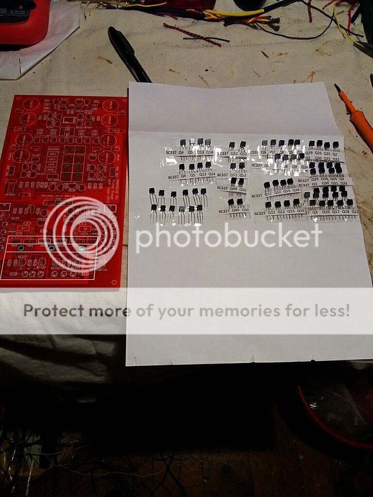
I bought this set of matched transistors for the Paradise but they are market Q12,Q14 and so on but there are no markings for Q12,Q14 on the pcb.
Is there a pdf or similar with the markings on the pcb?
I bought this set of matched transistors for the Paradise but they are market Q12,Q14 and so on but there are no markings for Q12,Q14 on the pcb.
Is there a pdf or similar with the markings on the pcb?

Check out the paradise thread, fdw has links in his signature to the reading list. The schematics for psu, pre-reg and amp sections are all there, you'll be able to fit the designations to the pcb overlay.
Resistors are soldered,now the caps.
I know there where a GB for "better" caps for the Riaa section,what where those caps and did they make a differens.(where they worth it?
I know there where a GB for "better" caps for the Riaa section,what where those caps and did they make a differens.(where they worth it?
There was a group buy for vcaps it was multi hundred dollar.
I have a very closely matched set of styrene caps for the riaa if you want them. 33 and 11n with wimas to add the last few pf.
£10+ p&p
I have a very closely matched set of styrene caps for the riaa if you want them. 33 and 11n with wimas to add the last few pf.
£10+ p&p
Yes they were Vcap CuTF, about $200 for a set if i remember right, i actually got them - but cannot tell if they are worth it - because haven't built one without them. But as it is with high end components - the minor improvement is very often not worth the price they cost - if you are not aiming for the very best. Also these were matched +-1% if i remember correct, that is a big plus though.
No multidollarsThere was a group buy for vcaps it was multi hundred dollar.
I have a very closely matched set of styrene caps for the riaa if you want them. 33 and 11n with wimas to add the last few pf.
£10+ p&p
;i cannot afford.. 😉
You got P.M
Hi,
have a look for the TE Con's LR1 1% and YR1 0.1% series at Mouser.
Both types feature thin films of a NiCr alloy, pressed on metal end caps and tinned copper wire legs for low money in 0207 casings.
jauu
Calvin
Thank you for the golden info 🙂
I guess it´s okay to substitute 2sk170 with 2sk117,same pinout.
I have done so in other builds I´ve done,I hope its okay here to as I have a bag of them..
I have done so in other builds I´ve done,I hope its okay here to as I have a bag of them..
Most people did build it long ago... but Frans have summed up all your questions/answers in post during time if you check a bit back in this thread.
I am connecting power to one channel for first time,everything seems fine ,except the output offset is fluctating beetween ca 40mv to -40mv I am using OPA627, is this sommething to worry about?
I am later going to install the buffer PCB.
Hope someone is still reading this thread. 🙂
I am later going to install the buffer PCB.
Hope someone is still reading this thread. 🙂
Ake, when you first power the Paradise up it takes about 70 hours of continuous running for the banks of el'caps to fully form. They only see a small voltage and as they form the DC offset begins to drop. You'll only drop to a couple of mV of dc drift once you have the Paradise in a box, it'll never get better than +/-10mV until it is fully cased up.
My builds used to start off at +/-100mV and settle down to 0.1mV> over the course of a few days.
The OPA 627 is a little better than the standard spec op-amp, but at significant cost. I'm not sure the difference is audible.
My builds used to start off at +/-100mV and settle down to 0.1mV> over the course of a few days.
The OPA 627 is a little better than the standard spec op-amp, but at significant cost. I'm not sure the difference is audible.
In my experience, the biggest output offset fluctuation comes from thermal drift of the input transistors. The servo has a time constant of about 1s, so anything faster will not be regulated away.... Try blowing on the input transistors and watch in awe what the output does 😀
In a box, the thermal drift is massively reduced. You could also glue a piece of copper foil on top of all input transistors, to reduce thermal airflow and couple them better....
In a box, the thermal drift is massively reduced. You could also glue a piece of copper foil on top of all input transistors, to reduce thermal airflow and couple them better....
- Home
- Source & Line
- Analogue Source
- Paradise Builders