Some more experiments led to confirming my suspicions that it is the cascaded CCS which is to blame for the 7MHz oscillations. Replaced it with a basic 317/337 based CCS set to 125mA and all is now well.
Not really sure how to cure this. Base stoppers? Would prefer not to dismantle the heatsink but if nothing else works would probably replace the CCS with an Ixys cascode.
Any ideas?
Hesener?
Not really sure how to cure this. Base stoppers? Would prefer not to dismantle the heatsink but if nothing else works would probably replace the CCS with an Ixys cascode.
Any ideas?
Hesener?
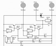
Can you post a part of the schematics, with values?
Pavel, please go to post 13 http://www.diyaudio.com/forums/analogue-source/218625-paradise-builders-2.html#post3189527
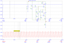
Wow. The simulated waveform is very similar to what i see on the scope. Seems like the simulation predicts something like 4MHz, right?
Wow. The simulated waveform is very similar to what i see on the scope. Seems like the simulation predicts something like 4MHz, right?
Yes it does, but I would rather call it indication only. That means, it could be 4MHz or 8MHz or something else depending on real transistor capacitances and PCB parasitic inductances/capacitance. It would be nice if you could try this simple modification and tell if it improves/worsens the situation.
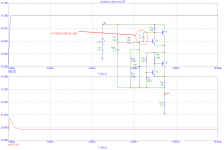
Just tried it. A bit short of time atm, so didn't do the right thing and use an smd but rather a 750pF polystyrene. Waveform changed a lot and became a lot more complex, while the principal frequency came down substantially. Should have probably tried much larger value caps as well but really pressed for time right now.
Thanks for the help!
Thanks for the help!
Some more experiments led to confirming my suspicions that it is the cascaded CCS which is to blame for the 7MHz oscillations. Replaced it with a basic 317/337 based CCS set to 125mA and all is now well.
Not really sure how to cure this. Base stoppers? Would prefer not to dismantle the heatsink but if nothing else works would probably replace the CCS with an Ixys cascode.
Any ideas?
Hesener?
O.K. (as Hesener said) this is interesting, we/I replaced earlier 317/337 based CCS's with the current CCS due to the fact that (nearly all that where build) of these 317's and 337's oscillated.
There have been numerous builds of the new CVS/CCS combinations and none of them did oscillate, I am real happy that you found out that it oscillates (and not the shunt, the CVS/CCS is easier to compensate and not speed critical (as the shunt)). This will help solve the problem.
It still is not clear to me why some are oscillating, most are not, there must be a reason/different that makes that most do not oscillate.
The most obvious way to stop these oscillations are:
1) Lowering the 330ohm resistors to 50ohm, this makes high Hfe less significant (but this was tried and did not work).
2) Adding compensation capacitors, these should go in parallel to BC of Q104, 204 if the CVS oscillates or/and BC of Q102, 202 if the CCS oscillates (as mentioned by Pavel).
3) [edit] Remove C93 (or replace with an 'low quality'/'high esr' 1u electolitic) (as mentioned by Waly),
@Pavel, good call 🙂 thanks for that.
I did/do prefere option 1 as it preserves the speed of the circuit.
Last edited:
Analog_sa, this is what I get. I will try to play with caps to compensate those local feedbacks.
@Pavel, what did you do to make/start it oscillate? My simulations in LTspice never indicated that the CVS would oscillate. Where the parameters added to the power source to do this. If any, I would like to know this, one is never too old to learn 🙂
Frans, I have added 1Vp-p step/square to the input DC voltage to simulate possible EMI transients. In my experience these are very tough cases to discover as they may or may not occur in praxis. In other words, in one place it may work fine and not in the other place.
1) Lowering the 330ohm resistors to 50ohm, this makes high Hfe less significant (but this was tried and did not work).
2) Adding compensation capacitors, these should go in parallel to BC of Q104, 204 if the CVS oscillates or/and BC of Q102, 202 if the CCS oscillates (as mentioned by Pavel).
Pull C93 at the servo and see if anything changes.
Frans, I have added 1Vp-p step/square to the input DC voltage to simulate possible EMI transients. In my experience these are very tough cases to discover as they may or may not occur in praxis. In other words, in one place it may work fine and not in the other place.
Thanks, I will try it/this (and some variations) (this evening) and report back.
Pull C93 at the servo and see if anything changes.
Good call, I never saw that one, I think you may be right. The specification for the 10u capacitor in the PSU was always 'low quality' e.g. 'high esr', and this capacitor (C93) contradicts that, and thus could make the shunt oscillate.
Pull C93 at the servo and see if anything changes.
Replace C93 by a 1u 'low quality'/'high esr' electrolitic capacitor?
Sandro called in today with his built up Paradise.
Right from the off the sound was excellent with great separation and good precision. bass is about as deep and extended as I've heard on vinyl, with exceptional texture and nuance all the way down to the bottom. Treble was similarly well resolved and brilliant without being overly etched. The sense of dynamic contrast that the paradise can portray is what really sets it apart for me, even with complex passages it never got bogged down or heavy. It kept a handle on things all the way through 'frame by frame' keep Fripp's guitar separate and positioned forward of Levin's stick bass and rendering all the time signature changes with perfect clarity. It never lost its way.
It's spurred me on to sort out the cases for my own sooner than i thought I would.
Great news from the court of the Crimson King 😀
No, it has nothing to do with the servo. The CCS oscillates with only the shunt following it and the actual amplifying circuit disconnected. Varying the CCS current had no effect either.
No, it has nothing to do with the servo. The CCS oscillates with only the shunt following it and the actual amplifying circuit disconnected. Varying the CCS current had no effect either.
O.k. thanks. But (as Waly noted) it may be a problem and we (the design team) needs to attend it 🙂
The reason is in local feedbacks with Darlingtons. There is a huge current gain and loops must be compensated. Tell me later a result with 10n or so, we also may try additional compensation caps. It will definitely get stable.
- Home
- Source & Line
- Analogue Source
- Paradise Builders