Sabbath, what transformers did you use?
Now I use 18 / 18 V AC from RS Components
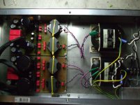
That picture was Beta PSU
I tried seletronic Race cores 24 / 24 but those have realy poor spec and voltagge was sky hi stay weel clear of those
Paradise sinks suplied on the goodies bag can not take the 24/24 but this can be solved with an extra CRC
IMO Idealy I wuld use 20 / 20 ac and same CRC
I got no pictures of the last ones
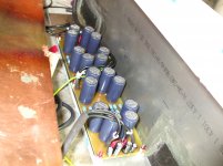
PSU with Race cores
and EXTRA CRC this mounted close bay to paradise boards
The details of my Build for R2 are here if you can put up with my frivolous spelling
http://www.diyaudio.com/forums/analogue-source/220354-my-paradise.html
Attachments
Last edited:
Hi guys,
I really appreciate your helping advices.
At first I built up a rectifire bridge like shown here:
Google-Ergebnis für http://www.vias.org/mikroelektronik/img/bridgerect.png
Now I have:
24,2 v dc
52,9 v ac
then I added a resistor (10k) and a capacitor (10000uF)
like it is shon here:
Google-Ergebnis für http://upload.wikimedia.org/wikipedia/commons/c/c2/Gleichrichter-Schaltung.svg
Now I have
37,3 v dc
81 v ac
This was for testing the dmm
Back to my board:
Next I added a load as Pavel (and Joachim) insisted,
5000 R parallel to the outputs (plus vdc to ground and
minus vdc to ground)
Now I have (each side)
35,9 v dc
78,8 v ac
parallel to the load.
I think there is something wrong,
I have to borrow another dmm for
checking.
Christoph
Christoph, I think you may believe DC measurement you made at the DC side of the power supply. And just forget the AC measurement that the DMM made on the DC part of the circuit. Some cheap multimeters make similar mistakes (= they do not separate DC from AC and then recalculate wrong - like twice the low pass filtered AC value, which in case of DC makes the AC error you have shown), I have experienced that before. In case you borrow another DMM, please try to have one that measures TRUE RMS (they have it indicated in specs sheet).
Last edited:
+1Christoph, I think you may believe DC measurement you made at the DC side of the power supply. And just forget the AC measurement that the DMM made on the DC part of the circuit. Some cheap multimeters make similar mistakes (= they do not separate DC from AC and then recalculate wrong - like twice the low pass filtered AC value, which in case of DC makes the AC error you have shown), I have experienced that before. In case you borrow another DMM, please try to have one that measures TRUE RMS (they have it indicated in specs sheet).
It happened to me before with a noname DMM
Ok, here we have the values measured by a novice (me)
with a professional dmm:
Output each rail is
36,8 v dc,
0,002 v ac
35,9 v dc with 5000 r in parallel.
With the 2x24 v transformator I have a little high dc I
think? Or is this fine and you give me a go?
Thanks for your great helping!!!!!!!!!
Christoph
with a professional dmm:
Output each rail is
36,8 v dc,
0,002 v ac
35,9 v dc with 5000 r in parallel.
With the 2x24 v transformator I have a little high dc I
think? Or is this fine and you give me a go?
Thanks for your great helping!!!!!!!!!
Christoph
That's ok, transformer and regulator are lightly loaded, so the winding resistance does not play its game.
With the real load, voltage will come down a bit.
It is high but I believe it will do not damage the shunts. (These will get quite hot but the heatsinks are quite beefy)
It is high but I believe it will do not damage the shunts. (These will get quite hot but the heatsinks are quite beefy)
I will measure my pre regulator today.
Hello Joachim,
have you found the time?
Best regards,
Christoph

My boards are finished, too.
The regulator is working fine, I could trim the input offset to 0mV but I have 2,5 and 2,7V at the external riaa and the output offset is fluctuating around underneath 1V.
I don't know if I should have the courage to connect it to my system😱
The regulator is working fine, I could trim the input offset to 0mV but I have 2,5 and 2,7V at the external riaa and the output offset is fluctuating around underneath 1V.
I don't know if I should have the courage to connect it to my system😱
- Home
- Source & Line
- Analogue Source
- Paradise Builders