what is the use of a Calvin Buffer? Sorry for my ignorance. I looked in the buffer's thread but I didn't get it
My 700+700 Bc ( plus the difference to 50 euros the minimum value for the order - a ERSA RSD 80) are on their way. To me. Are anyone using the Ersa RSD 80? I have been using some ERSA equipment and I'm content with it.
My 700+700 Bc ( plus the difference to 50 euros the minimum value for the order - a ERSA RSD 80) are on their way. To me. Are anyone using the Ersa RSD 80? I have been using some ERSA equipment and I'm content with it.
the calvin buffer can replace the onboard buffer, and has much stronger drive capabilities, sounds clearer and more detailed. The onboard buffer is very good, but this one is better especially when the line stage has low input impedance or long cables are used. It sounds clearer and more transparent, in my opinion.
does anybody know of a discrete output stage that at the same time does convert SE -> BAL? I would like balanced output since my amp is balanced input. Of course i could run it through a transformer, but that feels like the wrong way of doing it.
I think you can use a chip from That Corporation.
It sounds very good :
THAT Corporation 1606/1646 OutSmarts Balanced Line Driver ICs
It sounds very good :
THAT Corporation 1606/1646 OutSmarts Balanced Line Driver ICs
Thanks for the tip Joachim, but i would perfer any discrete solution, because i tend to think that IC's sound quite dull. Of course it would be possibly to try that IC, but then i could probably just use a transformer (which i already have).
I was just thinking if there was anybody sitting on a discrete se->bal driver stage design that could be used. Not for gain, but rather one less stage to add distortion.
I was just thinking if there was anybody sitting on a discrete se->bal driver stage design that could be used. Not for gain, but rather one less stage to add distortion.
Hi,
just add a differential stage ahead of two buffers, or..
add an inverter ahead of one of the two buffers.
jauu
Calvin
just add a differential stage ahead of two buffers, or..
add an inverter ahead of one of the two buffers.
jauu
Calvin
Hi,
just add a differential stage ahead of two buffers, or..
add an inverter ahead of one of the two buffers.
jauu
Calvin
Would you have a suggestion for a differential stage with a gain of 1? I kind of have the same issue.....
An externally hosted image should be here but it was not working when we last tested it.
It looks neat, but it doesn't make any difference that I can discern..
An externally hosted image should be here but it was not working when we last tested it.
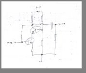
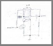
The 'house' slows down air flow (that's good) but you also need to connect (thermally) the transistors to each other. Take a small(thin) strip of copper and glue it (thermal conducting glue) over the top of the transistors. Thin copper is good, you do not want to add to much bulk (heat capacity) [and by that (much bulk) slow down the heat transport from the 'one' to the 'other'] 🙂
Hi,
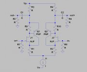
a differential amplifier stage with a gain reduced to 1 may be used ahead of the buffers as SE-to-Bal stage, or as fully differential stage.
One can feed it either in a balanced fashion, or in singleended fashion with one of the inputs grounded. The outputs may feed into Buffer stages.
Either of which Buffer outputs may be taken singleended or in differential mode.
In a simple form this may look like the circuit to the left.
The relationship between drain and source resistors defines the gain.
If equal resistors are used the gain becomes approximately -1 (inverting).
THD of such a stage is rather high at >0.1% (-60dB and higher) with a nice harmonic distribution.
Cascoding the JFET doesn´t improve THD significantely but reduces maximum output voltage.
Things change though if we use a CFP instead of the single input transistors, for example a JFET-Master controlling a PNP-slave, similar to the Calvin-Buffer.
This may reduce THD by 30-40dB against the simple stage, thereby preserving the good THD-Values of the Buffers.
jauu
Calvin
Attachments

Hi,
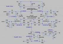
here´s an dimensioned example of the fully differential hybrid CFP gain stage in all-SMD style.
As input JFETs serves the LKS389C in SOIC8 again. As bipolar slave we find the Zetex FZT751 in SOT223. (both casings are quite easy to hand solder).
The audio signal is fed via a RC-lowpass (470R/470pF) into the JFET-Gates.
If the signal is not DC-free a series coupling cap would be required.
The tail current source is made up from Q3/Q4/R1/R9.
R12/C3 forms a power supply filter feeding into the tail-CCS. It also drops a couple of volts to reduce heat power.
The input of the tail-CCS is supplied via a JFET-CCS J3/R10 that is supplied over a RC power supply filter R11/C4 from the positive spower supply.
R14/15/P1 are paralleled to the Drain-resistors R6/R7 and allow to trim both outputs to equal amplitude.
R2a/r2b andR3a/R3b are the source resistors.
R16/R17/P2 form a similar arrangement as in the Drain-circuit but this time allowing to trim the gain. If not wished for omit with them and replace R2b/R3b with 68R.
C7 is a small compensation cap, reducing gain at HF, preventing possible oscillation.
C1 and C2 dc-block against the outputs and R8 and R13 are preloading resistors and bleeders for C1/C2.
The Gates of the Calvin buffer´s input-JFETs may be connected to the outputs, but omitting with the RC-input filters of the buffers.
Apart from the very short local current fedback loops the complete gain-stage+buffers would be global feedback free.
If one needs gain >1 the resistors in the source circuit may be lowered.
Also one can design a larger gain-trim range if desired by fudging with R16/R17/P2.
jauu
Calvin
Attachments
beautiful.... and, as Nelson Pass puts it: "If you don't like caps in the signal path - get over it" 🙂 I can see this becoming a great building block for all single ended sources.
Ideally, the SE-to-Diff converter would be DC coupled, that way it can replace the existing buffer and would then be included in the servo loop, so offset would be no issue (at least for one of the outputs). And if implementing a little gain would help with distortion etc, there is always the possibility to reduce the Paradise gain (by playing with the RIAA components) and allow a little bit in the output stage. This may change the sonic signature, though. Lastly, the supply voltages of the Paradise are +/-18V, from your schematic I am not sure what it is (-12V? the emitter voltage of Q4 seems off)
just my two cents....
Hi,
since I think, that the Buffer and SE-stage are worth their own discussion and may distract too much from the Paradise, I´d suggest to discuss details in the "Preamp-Buffers - simple idea" thread from Page15 on.
jauu
Calvin
since I think, that the Buffer and SE-stage are worth their own discussion and may distract too much from the Paradise, I´d suggest to discuss details in the "Preamp-Buffers - simple idea" thread from Page15 on.
jauu
Calvin
And a link to that thread - http://www.diyaudio.com/forums/analog-line-level/226099-preamp-buffers-simple-idea.html
- Home
- Source & Line
- Analogue Source
- Paradise Builders