Since the gates of the gain MOSFETs are assumed as somewhat relaxed virtual grounds due to the voltage-dividing resistors, I have estimated that the amp gain would be less than 10, but must be greater than 8, i.e. in-between 8 and 10 (20V rails).
I will try to measure the gain with my ZV5 as soon as I fly back to Shanghai this weekend . . . and will post the result in my thread . . .
As I promised at Audiorob's ZV5 thread,
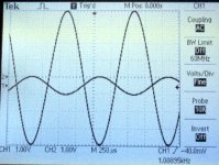
I measured the voltage gain at 1KHz as follows.
It is about 8 (18dB) if no error in my measure . . .
Attachments
Babowana said:
As I promised at Audiorob's ZV5 thread,
I measured the voltage gain at 1KHz as follows.
It is about 8 (18dB) if no error in my measure . . .
Hi Babowana,
Thanks for the reply and info.
1Vpp in, 8Vpp out, 8x gain. I'm getting about 6x gain.
I wonder why... I'm using IRF240 and 9240 FETs. I
think you mentioned that you are using something
else. I'm guessing that could be the reason.
Have you checked to see what your amplifier's full
output before clipping is (I'm interested in the max
peak to peak voltage), and what input voltage is
required to drive full output? For me, it was about
6Vpp in to drive 35Vpp out.
In my case, I have +-30V rails. Full output is a little
better than 17V. Again, I'm wondering why I cannot
drive the output voltage a little closer to rail voltage.
I'm also wondering why the spice models show
higher output voltage than I can achieve in the
practical world.
Thanks again,
Robert
Babowana said:
[>] Bias is only with 1.4A, but the sound is still good . . .
[>] Total big caps are of 6x33,000uF = 198,000uF per channel.
Can maybe be interesting to compare your Supply
with my Class A Designed Supply
Amplifier is based on TO3 transistors MJ211194, which are known to perform good at high currents and high power per device.
0.7 C/W 250 Watt TO3 transistors, Ft = 7 MHz
> Class A
> Trafo 30 VAC
> 38 VDC
> 2.0 Ampere
totally 76 Watt from supply per Channel
Simulated Output: Max 21.5 Watt RMS into 5 Ohm
Description and schematic of my output stage
in this topic:
My simple class a approach
I attach circuit here which very good shows MY SUPPLY.
I did not just add a lot of Capacitance by random.
I tried different combinations of resistors and electrolytic caps
to get the simulation to show as low Ripple as Possible.
It is so called RC lowpass filter.
Resistors will drop voltage with 1.32V,
but to get as low ripple ( milliVolts ) = CLEAN Supply as I got
It sure is worth it, to me, to lose 1 Volt or 2.
Enjoy!
My attachement!
Lineup Audio Lab Voltage Supply
lineup
Attachments
audiorob said:1Vpp in, 8Vpp out, 8x gain. I'm getting about 6x gain.
I wonder why... I'm using IRF240 and 9240 FETs. I
think you mentioned that you are using something
else. I'm guessing that could be the reason.
Have you checked to see what your amplifier's full
output before clipping is (I'm interested in the max
peak to peak voltage), and what input voltage is
required to drive full output?
I'm also wondering why the spice models show
higher output voltage than I can achieve in the
practical world.
Hi Robert,
I'm using IRFP250N and IRFP9240 of IR. I think that the voltage gain of ZV5 depends mainly on the R2/R1-ratio. In addition, the gain is affected by the value of R5 and R6 at certain degree. If sizes of R5 and R6 go down, the gain goes down too. For your info, my second approximation with the original R values calculates the gain of about 8.35X, which is similar as the measured 8X. If I'm doing right, I could assume that you are using R5 and R6 of lower values than the original . . .
I did not check the output V at the clipping point yet, but have a plan to do.
I have no idea about the spice models. Nevertheless, I believe that the spice models must be useful tools for initial designs of the circuits, but not for the confirmation of results of the final circuits.
Hoping my info will help . . .
Regards,
lineup said:It is so called RC lowpass filter.
Resistors will drop voltage with 1.32V, . . .
Thanks for the idea, lineup.
I will try CRCRCRC one day, not being afraid of the V drop . . .
Regards,
Babowana said:
Hi Robert,
I'm using IRFP250N and IRFP9240 of IR. I think that the voltage gain of ZV5 depends mainly on the R2/R1-ratio. In addition, the gain is affected by the value of R5 and R6 at certain degree. If sizes of R5 and R6 go down, the gain goes down too. For your info, my second approximation with the original R values calculates the gain of about 8.35X, which is similar as the measured 8X. If I'm doing right, I could assume that you are using R5 and R6 of lower values than the original . . .
I did not check the output V at the clipping point yet, but have a plan to do.
I have no idea about the spice models. Nevertheless, I believe that the spice models must be useful tools for initial designs of the circuits, but not for the confirmation of results of the final circuits.
Hoping my info will help . . .
Regards,
Hi Babowana,
I built a version of the Zen 5, per Nelson's paper, with the value of R1
= 475 ohms and the value of R2 = 4.75k ohms. That should yeild a
gain of around 10, but I not trying to ask about the gain factor. Well, I
guess I really am asking about gain, but not really gain factor.
I'm working on an op amp first stage, which will drive the "standard" Zen 5
amp. As this stage can have gain, I can increase R1 to increase the
damping factor (at the expense of this stage's gain factor). I've been
trying to model all this in spice. One of the things I notice in spice is that
I can have variations of this design where the amp outputs the rail voltage,
minus a couple of volts. In real life, I have not been able to get anywhere
near rail voltage, and I am trying to understand why.
So far, regardless of output stage gain and (reasonable) input voltage,
with plus and minus 30V rails, I do not get above 36Vpp output. With
the right gain settings and input voltage, I would have thought I could get
somewhere around 55Vpp voltage output (with +-30V rails). And the
spice models seem to indicate this can be done too. I'm wondering
where that other 20V has gone and why.
I hope that makes sense. But even if it doesn't, thanks for all the help.
Robert
BTW - I've built a couple of versions of a first stage. They really do make
the Zen 5 sound better. I'll probably be writing about them in my thread soon.
audiorob said:with plus and minus 30V rails, I do not get above 36Vpp output
. . . ???
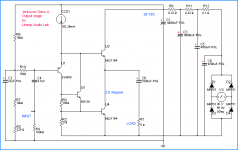
With +/- 20V rails, I get about 36Vpp output just at the start point of clipping.
For your info, attched plz have a look . . .
Attachments
Babowana said:
. . . ???
With +/- 20V rails, I get about 36Vpp output just at the start point of clipping.
For your info, attched plz have a look . . .
That is excellent information. Your amp acts as I would expect.
I wonder what I did wrong! 🙂
Thank you!!!
Babowana said:
With +/- 20V rails, I get about 36Vpp output just at the start point of clipping.
For your info, attched plz have a look . . .
As weird as this sounds (or, *I* do not understand this), this is what I have
discovered. With the "standard" (ie: per Nelson's paper) Zen 5, and re-biasing
for the different rail voltages:
+/- 20V Rails -> +/- 17V (34Vpp) output before clipping
+/- 25V Rails -> +/- 18V (36Vpp) output before clipping
+/- 30V Rails -> +/- 17.8V (35.6Vpp) output before clipping
I guess +/-20V rails is the sweet spot.
Does anyone have an idea why the output voltage does not rise above +/- 18V,
regardless of rail voltage? Could this be due to a max Vgs of 20V for the
IRFP240 and IRFP9240? I guess I need to trace voltages on the gate to see
if that might be it. Other than that, I'm out of ideas...
thanks,
Robert
BTW, if anyone cares to reply to the last message, please reply in the
"problems building zen 5 amp" thread and not here. I do not want to
take this thread in a different direction than what Babowana intended.
thanks,
Robert
"problems building zen 5 amp" thread and not here. I do not want to
take this thread in a different direction than what Babowana intended.
thanks,
Robert
audiorob said:BTW, if anyone cares to reply to the last message, please reply in the "problems building zen 5 amp" thread . . .
Having read your ZV5 thread, pleased that you solved the problem of no problem.
You're a computer-coded man . . . 😀
audiorob said:BTW - I've built a couple of versions of a first stage. They really do make the Zen 5 sound better. I'll probably be writing about them in my thread soon.
I'm intersted in your first stages.
I consider a good pre is enuf to be the first stage of ZV5, tho . . . 🙂
Babowana said:
I'm intersted in your first stages.
I consider a good pre is enuf to be the first stage of ZV5, tho . . . 🙂
One of my impressions of the "stock" zen 5 amp is that it decompresses
the input signal. By decompresses, I mean that quiet passages in music
played on the zen 5 are quieter than they normally are when played through
a commercial amp. Dynamic range is usually a good thing. However, I
think the zen 5 has too much of this effect. What I experienced was that
in some music, some of the background detail seemed to disappear, and
certain instruments stood out (or were more muted) than what I considered
normal.
Another impression was that for my speakers, the zen 5 needed more
damping factor.
And as we have already discussed (I think on the other thread), by
increasing the input impedance, you can improve the square wave
performance. I agree that we have no consensus about the relationship
between an amp's ability to produce square waves and the quality of the
amplifier's musical reproduction. But impedance balancing seemed like
a good thing to do.
Also, I had to put my X2 preamp in high gain mode to drive the zen (vs.
low gain mode when driving the X150, and most other amps). Yes, I
know - this is a rather trivial issue...
So I decided to build an input buffer or first stage. However, to do some of
the things mentioned above, the first stage needed to have some gain. So
I guess it is a first stage, and not an input buffer.
I'm starting with monolithic (IC type) op amps, but want to go towards a
descrete op amp design. So far, with monolithic op amps, I have
achieved all the goals above. Musically, I've had the best success with the
LT1028 (which has very low noise and THD, and also has class A/AB output).
I think my modified zen 5 sounds great (for MY use, and MY tastes, it does
sound better than the original zen 5 and on par with commercial amps), and
I"m still learning from it. Currently, I'm inputting 2.8Vpp (+/- 1.4V, +/- 1.5V
being somewhat of an industry standard), and getting 54Vpp before clipping.
This equates to about 68W peak or 48W RMS with 1kHz sine waves into 8
ohms.
Robert
audiorob said:. . . the zen 5 are quieter than they normally are when played through a commercial amp . . .
. . . for my speakers, the zen 5 needed more damping factor . . .
. . . I think my modified zen 5 sounds great (for MY use, and MY tastes, it does sound better than the original zen 5 and on par with commercial amps) . . .
I'm pleased to see that you in connection to the audio system are mentioning not about just sound but about the musical sound. Yeas, our ultimate target is getting nice musical sound.
I agree with you that ZV5 provides me with gentle and smooth music. Nevertheless, I do not miss details from the combination of ZV5 and J-low. This combination is much better than my previous combination of F1 and J-low. I had high pass filter when I was listening to F1 to kill honky in bass. But, I no more need that with ZV5.
Now, I'm listening to Cannonball Adderley. It is live recording, seems to be in somewhere a jazz club. I do not miss any timbre of instruments . . . sexophone, trumpet, piano, guitar, bass and drum . . . very nice in deed. I also get the heat of the real stage, and I feel like I'm seeing the players standing here and there.
Probably, I'm talking about my very subjective feeling . . . But, I know the sound of Pass X2 + Pass XA160 + Kharma and my headphone amp + Alessandro MS-2i . . .
I know you have your target to achieve.
Whatever it is, I believe you will get it, with your additional first stage.
Regards,
Attachments

Babowana said:I do not miss details from the combination of ZV5 and J-low. This combination is much better than my previous combination of F1 and J-low. I had high pass filter when I was listening to F1 to kill honky in bass. But, I no more need that with ZV5.
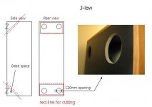
Mm . . . actually I did something new to J-low.
J-low has two dead corner spaces: upper and lower corners. And, the spaces are closed and empty inside. I introduced two 120mm openings to each closed space to make it an open space. Wow . . . and found very effective in bass (<120Hz) performance. For details of the openings, attached take a look at the sketch and the picture . . . The combination of ZV5 and J-low treated in this way . . . really very very good !!!
O, . . . one side effect of the openings is that I can use them as hand-grips when I move the location of J-low . . . 🙂
Dear Nelson,
I believe that proper handling of the closed dead spaces with openings (or filling them with sand or whatever) is a "must". I hope you would consider additional comment to your article when you have any chance. For me, the openings are much more effective than the high pass filter which is intended to remove the habit of honky bass. By the way, I don't know technically how the openings work . . .
Regards,
Attachments

Babowana said:By the way, I don't know technically how the openings work . . .
Hmm . . . I was just guessing that when there was music, there might have been standing waves at certain energy level inside the closed space. And, those standing waves might have been a cause of resonance peaks in bass frequency . . . Therefore, I just wanted to provide the openings to the closed space, wishing best luck in releasing the satanding waves . . .
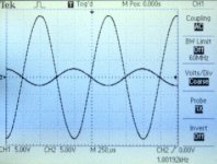
Back to ZV5, attached shows the upper critical frequency (-3dB) at about 110KHz, similar as 100Hz indicated in the Pass article. By the way, plz kindly understand that I am not trying to verify Pass work. 🙂 Actually, I'm practicing his design, checking the things I have done and trying to learn many valuable facts . . . 🙂
Attachments
you created sorta reversed Helmholtz resonators,in your case not for sucking unvanted resonances but for emanating sayed frequencies.......Babowana said:
Mm . . . actually I did something new to J-low.
J-low has two dead corner spaces: upper and lower corners. And, the spaces are closed and empty inside. I introduced two 120mm openings to each closed space to make it an open space. Wow . . . and found very effective in bass (<120Hz) performance. For details of the openings, attached take a look at the sketch and the picture . . . The combination of ZV5 and J-low treated in this way . . . really very very good !!!
O, . . . one side effect of the openings is that I can use them as hand-grips when I move the location of J-low . . . 🙂
Dear Nelson,
I believe that proper handling of the closed dead spaces with openings (or filling them with sand or whatever) is a "must". I hope you would consider additional comment to your article when you have any chance. For me, the openings are much more effective than the high pass filter which is intended to remove the habit of honky bass. By the way, I don't know technically how the openings work . . .
Regards,
you can stuff this cavities with some absorbant material for test;if you like it that way-leave it ,or you can then cut back plate pieces of these cavities,to open it and make non-cavities or non-resonant
what a sentence from ZM!
whoa!
Blue Car!

Attachments
Babowana said:
Thanks for the idea, lineup.
I will try CRCRCRC one day, not being afraid of the V drop . . .
Regards,
The CLC filters that Nelson uses is more effective filtering
than my used CRC.
Besides better filtering CLC also has lower voltage loss.
That is if you use THICK enough wire.
Thick wire has got lower resistance, Ohm, than thin wire.
But as with anything. There is two sides.
Advantages and drawbacks with any method.
Main advantages of using CRC or even like I do in my schematic,
CRCRCRC are:
You can buy and have a setup of low values ( 0.10 - 0.33 ohm ) power resistors in your lab.
They need not be more than like 2 - 5 watt rating = small power resistors.
If you then have also at home a supply of 4700 - 10000 uF electrolytic caps,
then you very quickly can put up a nice clean supply for any amp experiment.
---------------
The drawback with those very effective CLC filters are, as I see it:
- Takes time and effort to wound and make those big inductors.
You also need to have rather thick specially coated wire for this.
- Takes up a lot of space, as they are much bigger than 2- 5 watt resistors.
CRC are quick to put together and easy to change
and test different resistors values in combination with different caps.
And take up a rather small space in an amplifier box.
Having resistors also Protect Big Electrolyts from inrush currents at powering up.
Toroid trafos can have quite shocking first seconds behavior!
It will be a slow powering up, no overloading and this will give caps a bit longer life.
That Class A power supply shown
takes almost 1 minute before power supply caps have reach full working voltage
and I can run tests on that amplifier stage!
---------------
The power supply in my previous post up here
simulates in SPICE to give only 95mV ripple at 2A from 38 Volt DC (30 Volt AC Power).
With a reasonably big transformer, I would imagine a real value
would still be only a few 100mV ripple.
Which I consider a very good and clean Power Supply for Class A.
lineup
Zen Mod said:you created sorta reversed Helmholtz resonators,in your case not for sucking unvanted resonances but for emanating sayed frequencies.......
you can stuff this cavities with some absorbant material for test;if you like it that way-leave it ,or you can then cut back plate pieces of these cavities,to open it and make non-cavities or non-resonant
what a sentence from ZM!
whoa!
Blue Car!
Ah, Helmholtz resonators . . .
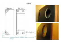
I was actually thinking about filling-in with stuff or entirely cutting-off the corners (along the red lines as you indicated). I have however given up the choice of cutting-off because I want to keep the current look of J-low. Of course, I could cut off the back panel of full square openings to make the air spring inside the cavities weaker even though I have considered the two 120mm openings as large enough.
I believe the filling-in stuff will be effective in dulling the air spring action inside the cavities. I am on the way to buy some stuff. I will see the result.
Cavities . . . I have thought only Dentist is using that word . . . He always welcomes my teeth and money, saying cavities, cavities . . . G damn it . . .
Filled in each space with polyester (silicone treated) fiber of 550g,
and attached the picture of it.
I did not carefully compare the sounds before and after the filling . . . Anyhow, both examples remove quite parts of boomy bass which I had with the closed empty corner spaces . . .
The bass became better pitch definition and better music's tonal foundation. Depending on music style, however, the quantity or the body of bass is a bit overflowing (due to poor recording?) . . .
Overall, I'm satisfied with the result. 🙂
Attachments
Babowana said:Filled in each space with polyester (silicone treated) fiber of 550g,
and attached the picture of it.
I did not carefully compare the sounds before and after the filling . . . Anyhow, both examples remove quite parts of boomy bass which I had with the closed empty corner spaces . . .
The bass became better pitch definition and better music's tonal foundation. Depending on music style, however, the quantity or the body of bass is a bit overflowing (due to poor recording?) . . .
Overall, I'm satisfied with the result. 🙂
fill it with even more
- Status
- Not open for further replies.
- Home
- Amplifiers
- Pass Labs
- Papa! I want to have Zen V5.