Sooo. I've had time and finally installed the TO-126 transistors BD441/BD442 as power transistors. And what can I say: once again much more full-bodied and cleaner and the drums cleaner and more contoured, the bass clearer, more punch, guitar and vocals too - listen above;-) And that with levels on my small 15 cm, 85 dB full range drivers in a 30 m2 room that I have to drum a 20 cm Doumbek really loud to make it audible;-)
By the way: this PA-940 should not remain a gym amplifier, but should be suitable for audio and home use, with plenty of reserves. It already is with the TO-220 transistors. And: it sounds significantly better than a Hiraga Le Monstre or Classe A. And other highly praised ones. The simple circuit and the components make it;-)
By the way: this PA-940 should not remain a gym amplifier, but should be suitable for audio and home use, with plenty of reserves. It already is with the TO-220 transistors. And: it sounds significantly better than a Hiraga Le Monstre or Classe A. And other highly praised ones. The simple circuit and the components make it;-)

Please show us a picture of the charred circuit board, when it finally happens.
My PA-940 is already in my country. I'm excited to hear and see what I find there.
Yes please share more pictures of the circuit boards and not just up close, every step is of interest as it will help to understand the modifications. Funny pictues of charred boards are welcome too ヾ(⌐■_■)ノ♪
Yes please share more pictures of the circuit boards and not just up close, every step is of interest as it will help to understand the modifications. Funny pictues of charred boards are welcome too ヾ(⌐■_■)ノ♪
I'll probably open my PA again tomorrow and take a few charcoal pictures;-)
At the moment, however, the thing is still running - contrary to "mathematical" predictions;-)
... or is it "mathematics" at all if it does not describe the observation, but only scribbles;-? See, for example, Ehrenfest Paradox;-)
At the moment, however, the thing is still running - contrary to "mathematical" predictions;-)
... or is it "mathematics" at all if it does not describe the observation, but only scribbles;-? See, for example, Ehrenfest Paradox;-)
Where did you say you GOT these BD441/2? I might want to try them and see if they really DO hold up on +/-50 volt rails driving a 8 ohm speaker directly. In my experience, no little 4 amp 40 watt device has survived the attempt**. Either someone is lying, or you could repackage them and sell them as 2SC5200’s. With better luck than the usual fakes with 2N3055 dies inside covered in white goop.
**ST:TOS, “The Corbomite Maneuver”, which may actually be applicable here.
**ST:TOS, “The Corbomite Maneuver”, which may actually be applicable here.
It's really interesting, because:
a BD422 cannot withstand an operating voltage of +/-50Vdc = 100Vdc -> Vce. Not even the good, genuine one from ONSemi ..!
a BD422 cannot withstand an operating voltage of +/-50Vdc = 100Vdc -> Vce. Not even the good, genuine one from ONSemi ..!
If voltage were the only concern I bet it would. Try connecting one to a 100 VDC supply collector-emitter, with base open. With a 100k resistor in series. Measure the current. I bet good money it’s negligible.
But turn up the volume enough and watch for fireworks. Half way up the rail you hit maximum instantaneous dissipation into a resistive load. This is the best possible case. 25 squared divided by 8 ohms is 78 watts. A 40 watt device will only take so many excursions of this before it tells you to eff off.
But turn up the volume enough and watch for fireworks. Half way up the rail you hit maximum instantaneous dissipation into a resistive load. This is the best possible case. 25 squared divided by 8 ohms is 78 watts. A 40 watt device will only take so many excursions of this before it tells you to eff off.
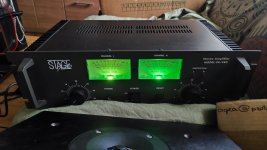
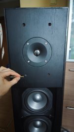
So, this thing of beauty is in my hands!
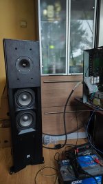
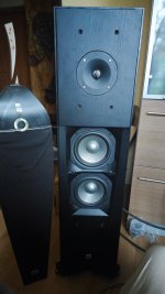
And finally my speakers are finally looking presentable enough to post on the forum even as not fully finished yet. The grills will be cut to fit and the screws will be painted black.
They sound amazing
And finally my speakers are finally looking presentable enough to post on the forum even as not fully finished yet. The grills will be cut to fit and the screws will be painted black.
They sound amazing
Attachments
In post #12 can someone explain what is meant by "bridging the pots". I understand if input is routed directly to amp boards, I can do that, but then I'm confused by "I replaced the first one with 100 kOhm" so is there or isn't there a pot in the signal path to the amp board?Then I bridged the pots. I replaced the first one with a 100 kOhm. Simply run the input cable directly from the input sockets to the amplifier board. This also brings a lot of cleanliness, silence and shine.
Also @hbtaudio how many TO-126 (BD441/BD442) in parallel do you think I'd need to not burn it immediately and perhaps be able to play without abuse or anything bass heavy vs how many for actual safe usage at full power at a party?
Hello there,
this is cumbbs thread, isn't it?
This user has put forward very strange theses that are completely incompatible with the laws (of electrical engineering, physics). I would prefer not to continue threads in the absence of this funny user.
"bridging the pots"[cumbb ?]
could mean “to bridge over” in German - ÜBERBRÜCKEN , i.e. to pass by. Perhaps he meant “to short (it), just a wire bridge”. Some of this gentleman's thoughts were somewhat absurd. It's a shame that he's no longer on board, but it was impossible to convince him.
Attachments
Solder the original SANKEN back in and be happy with your amp.
Sorry! Nevertheless, you can connect 10 of them in parallel and play with them a bit, who knows, maybe you'll get lucky ... Please don't forget RE and RB, a correctly dimensioned resistor in the emitter circuit and a resistor in series with the base electrode.
As a real alternative, turn your attention to the AB100 proposal from Nelson Pass and replicate it.
All the best,
HBt.
Typocorrectly dimensioned resistor in the emitter circuit and a resistor in series with the base electrode.
it must be read as CIRCLE or electrode.
Sorry.
Yes, I understand that a lot of what the gentleman said was contentious and he wasn't necessarily one to easily accept the contended thoughts. He must have been banned for saying something potentially dangerous. Believe me, if anyone misses him here, it's me. But anyhow, we don't have him anymore and the fact of the matter is that some of his ideas were not completely useless. In fact, as I have this amplifier right now already, it's actually a really good project. I still intend to do a few things (add more capacity to the power supply, perhaps change input and output coupling capacitors, improve internal wiring etc) I'll perhaps document both the changes I've made and the ones I'm going to do, to tell more about it. But the fact of the matter is, this cheap amplifier, with a few of the modifications cumbb suggested is really a pretty amazing little thing already.Some of this gentleman's thoughts were somewhat absurd.
I won't judge his character in the end (he should have been more careful how he phrased things given the contrarian nature of many of the things he liked to emphasize and convey), but I've tried and tested some of his recommendations other than what was shared in this thread and for me it has been both extremely educational and valuable in terms of sound discoveries.
Anyhow, thank you for contributing to this thread and to my understanding. Without the help of the banned gentleman my limited knowledge and experience allows me to go only so far. All help is appreciated.
Ok, I'll look into itAs a real alternative, turn your attention to the AB100 proposal from Nelson Pass
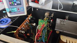
Btw on this PA-940 at Q4 I installed a three slot socket so I could change the transistors in around 10 seconds in this algorithm:
1. Turn off amp
2. Unplug current transistor
3. Install new transistor
4. Power on
And did a lot of testing (~50 or more changes between around 8 different batches and or types of PNP BJT TO-126 transes). Very very insightful. Indeed the gentleman was right - the differences and sound between the different batches of BD442 were profound, except I never had it done so easily and quickly. As a general rule the more doped ones (higher hFE) sounded better but not always. As for the original ones - they made much duller sound in this position. GREAT LITTLE EXPERIMENT! And proof of one of the concepts the controversial gentleman wanted to establish, even if he his tactics ended up getting him banned.
Anyhow - AMAZING LITTLE AMP! Indeed quite unbeatable for the price. I have many more amazing amps and projects of greater costs and qualities, but this thing will not become a dust collector on the shelf, I can tell already, it will see some use. Many would be surprised by how cool this is. So these are my words of encouragement if anyone wants to pursue the ideas in this thread (other than changing the output transistors, I'm still using the originals). But we can talk about potential alternatives.
Attachments
(...) Anyhow - AMAZING LITTLE AMP! Indeed quite unbeatable for the price. I have many more amazing amps and projects of greater costs and qualities, but this thing will not become a dust collector on the shelf, I can tell already, it will see some use. Many would be surprised by how cool this is. So these are my words of encouragement if anyone wants to pursue the ideas in this thread (other than changing the output transistors, I'm still using the originals). But we can talk about potential alternatives.
Why don't you give us a concrete indication of which screws you would like to turn?
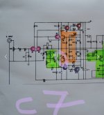
With this circuit (schematic of the amplifier-topology), you can let off steam as much as you like.
#
Tinkering with this teaching support (the PA-940 as a working basis) is ideal for gaining knowledge and expanding your own (specific) knowledge enormously. But only if there is a methodical-didactic concept, i.e. you receive guidance, a common thread, from an accompanying teacher. Otherwise you will end up with nonsense, which can, however, be a lot of fun and enjoyable.
Please forgive me if I tell you that “this remote seminar” must have a professional leader. I don't want to take on this task. Perhaps a coach can be found here in the forum, but I think it will have to stay with Q & A and trial & error.
In this standard circuit there are several main adjustment screws, all of which will change the respective sound impression, all of them. The final question is, can you also measure the result? After all, you don't want to stagger around in the dark of the universe, you also want to see something.
All the best and good luck,
HBt.
The only “screw” that need turning is that R10 is technically incorrect. Implementation without a bootstrap is wrong from a purely technical standpoint, although it MAY result in something that subjectively “sounds good”. Other than that the only thing I’d jack with is the ratio of R3 to R11 to ensure differential balance, after ensuring the match between the transistors is 5% or better. Because the folded cascode is resistive loaded as well as not using a CCS in the VAS or LTP tail there is probably no benefit to matching differential current down to .1%. But certainly make sure it’s not just totally out of whack, which it could be as stock.
I doubt I’d even mess with changing transistor types, unless something was bad and needed to be changed anyway or if you intended to do something silly with it like DJ or run 2 ohms load. For that there is only one choice IMO, and thats MJL21194 (and live with the fT reduction as it won’t matter there).
I doubt I’d even mess with changing transistor types, unless something was bad and needed to be changed anyway or if you intended to do something silly with it like DJ or run 2 ohms load. For that there is only one choice IMO, and thats MJL21194 (and live with the fT reduction as it won’t matter there).
Thank you guys for the recommendations and insights. I will review everything and see what I can do once I study it.
For now, I "bridged" the potentiometers, with very thin silver cores and my PSU hum is much louder. I'll try upgrading the power supply filtering. I also ordered some shielding materials for the wires. If nothing works I'll have to reconnect the volume control pots.
And another problem came up - high frequency crackling when 1VRMS DAC/pre output is raised to -30dB or more. ESPECIALLY on the speaker with (thick) silver cores for speaker cable. The other speaker has hybrid copper silver cable and it sees much less of this crackling, but still sometimes. I'll see what I can do, but any suggestions would be very welcome.
The way that things are grounded (what’s connected to what and where) more often determines how much hum you have than the condition of the power supply caps does. Usually, when the caps go bad you only develop hum problems under heavy load, and don’t put out full power anymore.
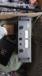
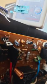
Well, this (see pic of right channel) actually solves at least 33% of my the noise, so with shielding, I should be pretty much good. But the original filter has really small caps for this kind of beefy device, only 6.8mF, so I'll add additional high voltage caps that I already have laying around.
BTW modifications done so far:
R24 and R23 - removed
Current limiter - removed (this is what makes this amp worthwhile)
Q4 - replaced with BD442, most likely any of them will sound better than original, but some batches (higher hFE usually)(which varies a lot) sound even better.
Volume pots - removed
Left channel ground wires connected to the amp section ground instead of protection circuit ground. Speaker output ground moved to amp section ground. (At this point I think I heard slightly Superior sound on Left channel. I was ABing using -30dB DSP on one channel.)
C7 replaced on left channel (KS-A 220 uF, 10 V) there is no doubt that left channel sounds better. Can someone please help me understand what voltage this cap is exposed to?
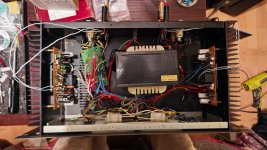
Added 15mF 80V cap on positive and the same on negative rail. Not even 0.2dB reduction in noise, which was 40.4dB in close proximity to the speaker. Soundwise it's definitely not detrimental, but it takes too long to attach and disconnect to be able to tell in confidence.
Crackling issue was a stupid mistake - I forgot to remove C10 C11 C12 C14. Idk the reason for C12 C14, they aren't current limiter and it wasn't mentioned ITT, but judging from pictures cumbb had them removed so I did the same.
Noise will hopefully be improved a lot by shielding input cables otherwise I'll have wrap the whole trafo in something or make a steel box. Aluminum wouldn't work, now would it? Easier would be just to move the trafo outside of the chassis.
Speakers are advertised by JBL to be 90 dB, but I'm pretty sure they're less sensitive.
BTW modifications done so far:
R24 and R23 - removed
Current limiter - removed (this is what makes this amp worthwhile)
Q4 - replaced with BD442, most likely any of them will sound better than original, but some batches (higher hFE usually)(which varies a lot) sound even better.
Volume pots - removed
Left channel ground wires connected to the amp section ground instead of protection circuit ground. Speaker output ground moved to amp section ground. (At this point I think I heard slightly Superior sound on Left channel. I was ABing using -30dB DSP on one channel.)
C7 replaced on left channel (KS-A 220 uF, 10 V) there is no doubt that left channel sounds better. Can someone please help me understand what voltage this cap is exposed to?
Added 15mF 80V cap on positive and the same on negative rail. Not even 0.2dB reduction in noise, which was 40.4dB in close proximity to the speaker. Soundwise it's definitely not detrimental, but it takes too long to attach and disconnect to be able to tell in confidence.
Crackling issue was a stupid mistake - I forgot to remove C10 C11 C12 C14. Idk the reason for C12 C14, they aren't current limiter and it wasn't mentioned ITT, but judging from pictures cumbb had them removed so I did the same.
Noise will hopefully be improved a lot by shielding input cables otherwise I'll have wrap the whole trafo in something or make a steel box. Aluminum wouldn't work, now would it? Easier would be just to move the trafo outside of the chassis.
Speakers are advertised by JBL to be 90 dB, but I'm pretty sure they're less sensitive.
Attachments
Last edited:
- Home
- Amplifiers
- Solid State
- PA-940 - Mc Crypt, Better, Sun Key, Stage Audio, JB Systems...