Thanks Perry,
I will have to dig a little deeper to find it. I may have to removed board, as they may be on the other side.
Good evening
Mike
I will have to dig a little deeper to find it. I may have to removed board, as they may be on the other side.
Good evening
Mike
Desolder and replacing it would be my course of action. I wouldn’t bet another set of mosfets on the integrity of the wiper contact after pulling the epoxy off.Is there a trick to getting the epoxy off the pots for adjustment?
I experienced symptoms that would come and go without any pattern. The DC offset would dance around +/-15mV and occasionally turn to thunder. In my case, it was corrosion/tarnish on a DC setting potentiometer wiper, so I replaced them on both channels with modern o-ring sealed types. If that had happened on the idle current setting pots it would have been terminal.It could be a bad pot. It's relatively rare but it happens.
So as I suspected, the ro transistors are on the other side of the board. As you stated Perry they are connected to the center terminal of the pot.
OK. Do not spray those with the canned air.
If you didn't know, inverting the can will dispense liquid refrigerant and chill anything it hits.
Try heating and pushing at the same time to see if you can get the voltage across the resistors to vary.
If you didn't know, inverting the can will dispense liquid refrigerant and chill anything it hits.
Try heating and pushing at the same time to see if you can get the voltage across the resistors to vary.
I did know that about the canned air.
Hitting anywhere near the pot with heat drops the mv across the the resistor dramatically. This all without pushing or pulling on anything. That being said. The other channels are behaving the same when heat is near the pot.
I get a bit nervous without the mosfets being clamped down because the 317t gets quite hot.
In order to get under the board I had to pull the board out of the heat sink. ( to access the bias transistor.
I thought you wanted me to heat near the RO transistor. Anyway all back in its home and clamped back up. The bias voltage definitely responds to heat but so are the others I put heat on.
The only reason I wanted to know where it was was to prevent you from spraying it with the refrigerant. That could make the idle current spike.
Between heating and cooling and pushing, I was hoping that you could find an intermittent problem.
Instead of just pushing, did you try tapping?
Between heating and cooling and pushing, I was hoping that you could find an intermittent problem.
Instead of just pushing, did you try tapping?
Great idea! I will try that.
What are the chances of an intermittent issue with a driver transistor staying hi whe it should be low possibly creating a short between the pnp and npn?
Just spitting out ideas
What are the chances of an intermittent issue with a driver transistor staying hi whe it should be low possibly creating a short between the pnp and npn?
Just spitting out ideas
At this point, I don't know. It's the randomness of the problem that makes finding it difficult.
Is it possible that you inadvertently solved the problem the last time you repaired it?
If we can't find an intermittent problem... If you can go without playing it loud for a while, install a 15 amp fuse in it and reinstall it. The 15 amp fuse may protect the components so you just have to do more troubleshooting and not replace parts.
Are all of these replacements from a reputable distributor (NOT amazon or ebay)?
Thanks Perry,
They are all from DigiKey. I don’t trust eBay or Amazon etc… for these items.
I think I will do as you say and put a small fuse inline for a while. It never made a difference whether it was loud or quiet when it shorts. When I opened it up the fets were shorted and the 0.1 ohm resistors were both discolored. Also the other side of the board has the surface mount r050 resistors that opened (burned out) at 2 different times.
One thing for certain is that it happens within 5 minutes after turning on. After that if it doesn’t blow it’s good all day.
Strange
16 in total
2x 3615 and 2x 5210 per channel
I will set the bias on all to 1mv. As I have no specs.
2x 3615 and 2x 5210 per channel
I will set the bias on all to 1mv. As I have no specs.
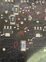
The 0.05 ohm SMD resistors (2 in series?) could be in parallel with the 0.1 ohm through-hole on the top pf the board for the parallel output transistors.
Hi Perry,
I just got home from work. You are right the smd resistors are in parallel.
I’m going to try more heating and cooling to see if I get anything funny.
So far heating up the area near the pot and fets (hard to isolate the heat) lower the current from about 1mv down to .3mv within seconds.
I wonder if it’s possible that the push pull drivers could be an issue. I do have those transistors. I wonder if I should change them out on that channel?
What I was looking for from the heating and cooling was something that was going to try to cause the amp to fail, like a heat sensitive component but there doesn't appear to be any.
Heating of the bias transistor (through the board) is supposed to drop the idle current. The bias transistor compensates for the properties of transistors that make them pass more current (when passing minimal current) as they heat up. During normal operation, without a bias compensating transistor, the current of the amp would do just the opposite of what you see when heating the bias transistor. Eventually, as the amp heated up in a sort of snowball rolling sort of way, it would self destruct.
I can't recommend replacing parts without a good reason.
Hi Perry,
Just an update
I have done the heating and cooling with idle at 1mv on the bad channel.
Heating does as you stated and cooling down to frost with the air can took it to around 14mv which quickly dropped.
I did push all around the board and noticed no significant changes in voltage across the resistor.
Amp is currently running again for now.
Do you figure 1mv on all channels at around 70deg Fahrenheit should be ok?
Thanks
Mike
1mv should be OK and it should hold at all temps. That's what the bias circuit does. Not all are perfect but most are pretty close. There's nothing stopping you from running the amp hard enough to get it hot (normal operation, not spot heating) and re-check the bias. If you do this, check the biasing at several points as the amp heats and cools.
If you're concerned, run a 20kHz signal through the amp (about 1v at the loaded speaker terminals) and see if the signal is distorted.
If you're concerned, run a 20kHz signal through the amp (about 1v at the loaded speaker terminals) and see if the signal is distorted.
- Home
- General Interest
- Car Audio
- P600x4 keep blowing same channel