hi
i have constructed a P3A amp and when i powerd it up the replace transistors C546 burned. (i understand that that was the problem with the transistors)
after that i have build the amp again using new part (others) and I get 33V on output.
I am using BD249C & BD250C with BD139/140 and BC546A.
I measured the voltage and all the results are presented in the picture:
i have constructed a P3A amp and when i powerd it up the replace transistors C546 burned.
(i understand that that was the problem with the transistors)after that i have build the amp again using new part (others) and I get 33V on output.
I am using BD249C & BD250C with BD139/140 and BC546A.
I measured the voltage and all the results are presented in the picture:
Attachments
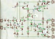
You have a fault with your input stage most likely, the voltage at the emitters of the LTP should be about 0.65 below ground, not several volts above ground.
Hi,
the reverse voltage on BE of Q7 and the 3.7Vbe of Q8 probably mean both these are damaged. Replace carefully. Do you sink the small device legs while you solder? I don't and I get away with it. I know I should!!
That 1.1V across the multiplier may indicate that the output stage is undamaged.
Why is there only 6.9V across the DC blocking NFB cap? Is it leaking badly or damaged or is that normal for a high output offset? C4 is back to front. It is normally biased the other way when the circuit is operating correctly. That probably explains the ONLY 6.9V across it.
check Q 6, 7, 8 for shorts or incorrect leg positions. Also check LED1, R5 and R6 for incorrect values or open circuits. Your bias servo seems to be working right and the output stage also so check the front end of the amp.
Hi adi81bv,
The voltages around your diff pair are normal for this fault condition. They have been damaged. They may still work but the hFE may have shifted and they will be noisier than they were. Replace for that reason and match for beta. Andrew is correct in that your emitter voltages should be approximately -0.65 VDC from a ground reference.
Q3 appears to be biased on but should be off (ie 0.00 VDC from emitter to base). You should check it to make sure it isn't shorted, also check that R4 is soldered properly and measures correctly. If Q1 was shorted or your output, you may get these readings also. However, Q3 should be off and it could be Q7 in reverse breakdown.
Thermally couple Q7 and Q8 when you replace them with a matched pair.
-Chris
i verified every transistor. hFE, and resistance - they all seem to work fine. I verified 4 times the tracks and the solder. I verified the correct soldering of the transistors on the pcb.
anyone have another ideea? i dont know to much electronics.... i was told that this is a easy amp to build, but i build 2 of them and both are dead. 🙁 dont know what to do....
anyone have another ideea? i dont know to much electronics.... i was told that this is a easy amp to build, but i build 2 of them and both are dead. 🙁 dont know what to do....
Hi adi81bv,
-Chris
At least you are consistent. There is something that you think is right, that is not. At this point you need someone more familiar with electronics to look over what you have done. Perhaps if you could take a picture of your work and post it?i dont know to much electronics.... i was told that this is a easy amp to build, but i build 2 of them and both are dead. dont know what to do....
-Chris
i checked R13. it is correctly soldered. may be the transistors? there can not be the resistors (it's the second amp that i am building; the first didn't work either and i changed the pcb and all parts) i measured all the resistors prior to soldering and checked 3 times the circuit for correct alignment and short-circuit.
Attachments
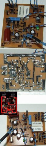
hi. i decided to build a 3'rd amp. the 1'st was done with bad components (i am certain). The second which is posted in the picture above i will try to figure it out later.
So I will go buy the parts for the 3'rd amp. BUT, i would like some of you to guide me through the process. I will put pictures to be more explicit.
Fist I will make some photos to the components for you to guide me if they are fake transistors or no. Any suggestion is welcome.
PS. sorry for my English and be patient because i am new to electronics 🙂
Hi adi81bv,
There is a thread on real and fake transistors. Have a read.
Buy your parts from known larger supply companies. It is more likely you will get real parts.
-Chris
There is a thread on real and fake transistors. Have a read.
Buy your parts from known larger supply companies. It is more likely you will get real parts.
-Chris
As Andrew pointed out a few posts ago, C4 is reverse biased and very leaky (there should be no DC drop across R8, because no DC should be flowing through C4.) A leaky or shorted C4 will still sort of allow a working amp to work, it just will not take DC gain to unity.
If (when) the cap blows open, you have no feedback and the amp will not function.
When you get done with transistor swapping, check all your caps for overstress.
- bkb
If (when) the cap blows open, you have no feedback and the amp will not function.
When you get done with transistor swapping, check all your caps for overstress.
- bkb
Hi Ken,
The root of the problem seems to be an output condition that the differential pair could not correct. So the cap and several other parts are what we could call collateral damage. The cap is but a victim, not the cause.
-Chris
The root of the problem seems to be an output condition that the differential pair could not correct. So the cap and several other parts are what we could call collateral damage. The cap is but a victim, not the cause.
-Chris
You haven't accidently put the wrong polarity devices in on the front end? Re-check your diff amp transistors - also check that you have sired them, in correctly wrt Base, emitter and collector. Seems you have a problem in the front end you need to fix.
Good luck.
Good luck.
hi thank you for helping me. for the moment i will build another amp, with new parts and a new pcb. after some searching on the internet i believe that the parts that i used where not good. i hope that the new amp will work fine.
after that i will try to repair this one. for the moment i will leave it this way and concentrate on building the new amp. anyway i will need 2 amps in the end.
again thank you for helping me.
_____________________________________________________
I have some questions about the amp>
1.should i use instead of BC546A, BC546C or BC639???
2.VR1 can be 2k2? i didn't find 2k pot. if it needs to be 2k i will use the one from the other amp.
3.the 100n cap's should be ceramic? but the 100p and 200p cap's? And should i put another 100p cap between B-C of the BD139?
Hi,adi81bv said:1.should i use instead of BC546A, BC546C or BC639???
2.VR1 can be 2k2? i didn't find 2k pot. if it needs to be 2k i will use the one from the other amp.
3.the 100n cap's should be ceramic? but the 100p and 200p cap's? And should i put another 100p cap between B-C of the BD139?
BC546a is the lowest gain, they usually come in 546b. The 546c is very difficult to source. But there was a group buy many months ago, I think he has many left to sell on. The price for a nearly unobtainable part was very good.
If you really need Cgrade then bc550C is very easy to obtain but it is only a 45Vce0 device.
2.) 2k2 pot =2kpot. The tolerance on these is usually +-10%.
3.) Many do not like ceramic carrying audio signals. Some get very upset when I suggest that constant voltage rail to ground glitch suppression caps can be ceramic. They are very cheap to try, then build one amp with film caps in this location and listen/measure for differences.
Do not add an extra 100pF//100pF across the bd139. maybe adjust it +-25%
thank you.
about the BC546, i also have some BC639 home. If you think that they can do the job right, I could use them. If not, i will put BC546A like Rod suggested on his site.
about the BC546, i also have some BC639 home. If you think that they can do the job right, I could use them. If not, i will put BC546A like Rod suggested on his site.
bc546 are the unsorted off the production line.
These will have a big range of components characteristics. Some good and some bad. You select and choose matched sets.
I think the bc546a is the rubbish left over after all the good ones have passed the parameter tests and they sell them off cheap for non critical use.
I would never select BC5xxA and certainly not for the front end LTP.
did you search 546c?
http://www.diyaudio.com/forums/showthread.php?s=&threadid=7889&highlight=
http://www.diyaudio.com/forums/showthread.php?postid=990364#post990364
It is Bob who has a good stock of cheap bc546c. Buy at least 25pairs to allow you to find matched pairs. test Vbe AND hFE @ the operational Ic. Select for Vbe <+-1mV and hFE <+-5%.
- Status
- Not open for further replies.
- Home
- Amplifiers
- Solid State
- P3A problem