Thank you Paaji,
Waheguru Ji Ka Khalsa, Waheguru Ji Ki Fateh
Regards
Prasi
Sorry mods, I tried google translate but doesnt work, so here is the link for explanation
Waheguru Ji Ka Khalsa Waheguru Ji Ki Fateh - SikhiWiki, free Sikh encyclopedia.
Waheguru Ji Ka Khalsa, Waheguru Ji Ki Fateh
Regards
Prasi
Sorry mods, I tried google translate but doesnt work, so here is the link for explanation
Waheguru Ji Ka Khalsa Waheguru Ji Ki Fateh - SikhiWiki, free Sikh encyclopedia.
Thank u sirYou can download the pdf's here.
Filebin :: bin fsldfnieivrr8mdm
But hurry, files will be available only for 1 week.
regards
prasi
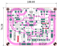
Build this one, it will work properly. its based on Adi_007 layout.
What is input capacitor c12 value.and q9 on which heat sink and how fix(will stuck)
Build this one, it will work properly. its based on Adi_007 layout.
Dear sir
Is it necessary to connect bd139 and bd140 with heat sink.and what the value of c12 and c13 in above circuit /pcb layout.thanks regard.
C1/C12/C13 are one and the same and are options for the input coupling cap.
C1 is an electrolytic
C12 is film cap with 22.5mm pitch
C13 is also a film cap with 15mm pitch.
Use any one only.
Yes all bd139/140 on the same heatsink and also the bc547 (Q9).
see attached image. It can be a 1 to 1.5 mm thick aluminium plate of 63.5 length and 50mm height.
C1 is an electrolytic
C12 is film cap with 22.5mm pitch
C13 is also a film cap with 15mm pitch.
Use any one only.
Yes all bd139/140 on the same heatsink and also the bc547 (Q9).
see attached image. It can be a 1 to 1.5 mm thick aluminium plate of 63.5 length and 50mm height.
Attachments
Thanks dear.i want to ask how can bc546 can be mount on heat sink.if you dont mind please send me your whatsapp no.pleaseC1/C12/C13 are one and the same and are options for the input coupling cap.
C1 is an electrolytic
C12 is film cap with 22.5mm pitch
C13 is also a film cap with 15mm pitch.
Use any one only.
see attached image. It can be a 1 to 1.5 mm thick aluminium plate of 63.5 length and 50mm height.
Sorry, No number , I like to remain anonymous.
flat surface of Q9 should have tiny amount of heatsink paste. press down on heatsink and Wipe the oozing paste and then You can stick the BC546 to the aluminium plate with a drop of feviquik glue/ fevicol/ rubber solution / glue gun at the edges of bc546.
flat surface of Q9 should have tiny amount of heatsink paste. press down on heatsink and Wipe the oozing paste and then You can stick the BC546 to the aluminium plate with a drop of feviquik glue/ fevicol/ rubber solution / glue gun at the edges of bc546.
Last edited:
Sorry, No number , I like to remain anonymous.
flat surface of Q9 should have tiny amount of heatsink paste. press down on heatsink and Wipe the oozing paste and then You can stick the BC546 to the aluminium plate with a drop of feviquik glue/ fevicol/ rubber solution / glue gun at the edges of bc546.
Dear Are you Subhash chandra bose .wants to live anonymous.
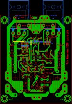
This is sending current pulses on V+ and V- all around the circuit. Not exactly the definition of low inductance.
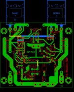
Good power amp layouts tend to be elongated and carrying V+ and V- next to each other along the heatsink. I would definitely advise routing both rails on one side.
Good power amp layouts tend to be elongated and carrying V+ and V- next to each other along the heatsink. I would definitely advise routing both rails on one side.
Hi Sgrossklass
Im not expert pcb maker.. But i m learning quickly..
So give us an example, not a full pcb.
My P3A sounds perfect.... Full bass and detailed...
Also my measurements with load and sine wave and square wave on scope are also very good. I will posting my measurements tomorrow. Thanks again.
.
Im not expert pcb maker.. But i m learning quickly..
So give us an example, not a full pcb.
My P3A sounds perfect.... Full bass and detailed...
Also my measurements with load and sine wave and square wave on scope are also very good. I will posting my measurements tomorrow. Thanks again.
.
Attachments

Hi Sgrossklass
Im not expert pcb maker.. But i m learning quickly..
So give us an example, not a full pcb.
My P3A sounds perfect.... Full bass and detailed...
Also my measurements with load and sine wave and square wave on scope are also very good. I will posting my measurements tomorrow. Thanks again.
.
Dear
If you dont mind plz.share its pdf.thanks
Hi Sgrossklass
Im not expert pcb maker.. But i m learning quickly..
So give us an example, not a full pcb.
My P3A sounds perfect.... Full bass and detailed...
Also my measurements with load and sine wave and square wave on scope are also very good. I will posting my measurements tomorrow. Thanks again.
.
Nice build, where is the star ground and chassis connection?
Last edited:
Dear
If you dont mind plz.share its pdf.thanks
Sure.., just give me your email address by pm..
Sure.., just give me your email address by pm..
My email is...alvi.masood251@gmail.com
Masood251, PM means private mail - be careful and keep your mail private by never disclosing yours or other people's private email address on a public network.
DiyAudio has a PM format just like the forum, for all members to use. Just select "User CP" on the menu bar and a control panel menu will drop down for you to organise your private mail and replies .
DiyAudio has a PM format just like the forum, for all members to use. Just select "User CP" on the menu bar and a control panel menu will drop down for you to organise your private mail and replies .
Ok dearMasood251, PM means private mail - be careful and keep your mail private by never disclosing yours or other people's private email address on a public network.
DiyAudio has a PM format just like the forum, for all members to use. Just select "User CP" on the menu bar and a control panel menu will drop down for you to organise your private mail and replies .
I will try to use cp at menu bar
- Home
- Amplifiers
- Solid State
- P3A layout