Just post your work. With all due respect to Rod Elliott who has contributed much to the DIY community, the P3 and P3A are derivatives of a generic topology. If Rod didn't want further derivative work he wouldn't have posted the circuit in the public domain.
Frankly it still all greek to me, may be also because I am not EE. no matter what i do i always ended up with hum when i used amp and peramp in same enclosure. individually the amp was super quiet when driven with a cd player. http://www.diyaudio.com/forums/solid-state/277695-grounding-issues-integrated-amp.html#post4402957
i am 50 today i construct amplifiers since i was 13 i had hum issues last time i was 14 i think
I took a brief look at your drawings and i think that you placed star ground in th wrong place
I also think that a good starting point will be to disengage mains ground from audio ground to see not many things can be done from a drawing ...
I took a brief look at your drawings and i think that you placed star ground in th wrong place
I also think that a good starting point will be to disengage mains ground from audio ground to see not many things can be done from a drawing ...
One of the biggest lessons to be learned from that "grounding" Thread is that the use of the word "ground" is the biggest sin we commit.Frankly it still all greek to me, may be also because I am not EE. no matter what i do i always ended up with hum when i used amp and peramp in same enclosure. individually the amp was super quiet when driven with a cd player. http://www.diyaudio.com/forums/solid-state/277695-grounding-issues-integrated-amp.html#post4402957
Stop using the word "ground" and refer to each signal Return wire/trace/route by it's correct and unique name.
Most of our "grounding" problems occur because we join together different parts of the circuits incorrectly because so many here and everywhere else mis-use the "ground" word and we get led into the trap that creates the interconnecting problem.
Stop using the "ground" word.
i am 50 today i construct amplifiers since i was 13 i had hum issues last time i was 14 i think
I took a brief look at your drawings and i think that you placed star ground in th wrong place
I also think that a good starting point will be to disengage mains ground from audio ground to see not many things can be done from a drawing ...
I respect your zeal and dedication. I wish to have the same dedication too.
One of the biggest lessons to be learned from that "grounding" Thread is that the use of the word "ground" is the biggest sin we commit.
Stop using the word "ground" and refer to each signal Return wire/trace/route by it's correct and unique name.
Most of our "grounding" problems occur because we join together different parts of the circuits incorrectly because so many here and everywhere else mis-use the "ground" word and we get led into the trap that creates the interconnecting problem.
Stop using the "ground" word.
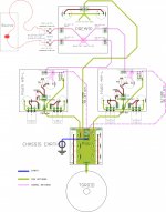
Yes Andrew, We should call it either reference or return. here is my take on "referencing" for a chassis mounted amp that has more than one signal processing circuits, i.e., pre and power both. I have just shown the references/returns wiring/traces; your other recommendations remain valid and should be followed (like twisting of high current wires, shileding of i/p cables, etc.)
I have shown a very very simplified form of wiring, but is the basic concept correct? Would like to have yours and Jeff's comments please.. It is definitely not a universal one, so should not be thought of as a recipe by others, but it is intended to give the general idea on how to treat signal and power circuits.
Is it necessary / advisable to clearly identify which components go to signal returns and which components are connected to PSU returns at design stage itself by the designers?; would that simplify the problems with hum and other things that pester newbie diyer's?
reg
Prasi
Attachments
That looks right,
But I have to add a "but":
The close coupled Flow half is not shown adjacent to it's Return.
That is an important part of any two wire signal connection between modules.
But I have to add a "but":
The close coupled Flow half is not shown adjacent to it's Return.
That is an important part of any two wire signal connection between modules.
That looks right,
But I have to add a "but":
The close coupled Flow half is not shown adjacent to it's Return.
That is an important part of any two wire signal connection between modules.
Thanks Andrew. I know, flow always goes along with its return, just wanted to simplify the scheme so that its easy to understand all. Like I said all your other recommendations remain same and have to be followed.
reg
Prasi
Yes Andrew, We should call it either reference or return. here is my take on "referencing" for a chassis mounted amp that has more than one signal processing circuits, i.e., pre and power both. I have just shown the references/returns wiring/traces; your other recommendations remain valid and should be followed (like twisting of high current wires, shileding of i/p cables, etc.)
I have shown a very very simplified form of wiring, but is the basic concept correct? Would like to have yours and Jeff's comments please.. It is definitely not a universal one, so should not be thought of as a recipe by others, but it is intended to give the general idea on how to treat signal and power circuits.
Is it necessary / advisable to clearly identify which components go to signal returns and which components are connected to PSU returns at design stage itself by the designers?; would that simplify the problems with hum and other things that pester newbie diyer's?
reg
Prasi
Hi Prasi.
I try to follow AndrewT's advice for wiring an amp, so my advice would be no different.
OK, lets look at what happens in stereo configuration. follow the purple dash-dot line along the i/p return. is it creating a loop? Also, if the source has common reference for left and right channels, does it also create a loop? (follow the bright red line at i/p connection)
reg
prasi
edit: If it is leading to too much divergence from the subject of this thread, I will move it elsewhere.
Also, to look up the image completely, you may like to save it to local hard-drive and open with your image viewer.
reg
prasi
edit: If it is leading to too much divergence from the subject of this thread, I will move it elsewhere.
Also, to look up the image completely, you may like to save it to local hard-drive and open with your image viewer.
Attachments
Last edited:
Hi prasi
I built a p3a amp. Wiring of the "returns" was not so accurate, but i had a loop noise when both channels were connected. In my opinion, your good layout can reduce the noise of the amp but that input loop is unsolvable. Only using resistors in the path of signal return to separate signal and power path may help.
Or the other option is dual mono obviously.
Yes I can see the loop around the purple route.OK, lets look at what happens in stereo configuration. follow the purple dash-dot line along the i/p return. is it creating a loop? Also, if the source has common reference for left and right channels, does it also create a loop? (follow the bright red line at i/p connection)
reg
prasi
edit: If it is leading to too much divergence from the subject of this thread, I will move it elsewhere.
Also, to look up the image completely, you may like to save it to local hard-drive and open with your image viewer.
Remove the broken purple lines.
Look, you still have a loop. But this time the loop includes the 10r||D||D in each half. That 10r is the solution given by D.Joffe. He shows exactly this loop problem in a stereo implementation and it applies to any multichannel amplifier where two or more interconnects use a common ground at the remote source equipment.
Dual mono does not remove the loop.Hi prasi
I built a p3a amp. Wiring of the "returns" was not so accurate, but i had a loop noise when both channels were connected. In my opinion, your good layout can reduce the noise of the amp but that input loop is unsolvable. Only using resistors in the path of signal return to separate signal and power path may help.
Or the other option is dual mono obviously.
Only a monoblock with ONE interconnect can avoid this external loop through the source.
The Loop problem is solveable. Read D.Joffe.
This is wrong. This is the mistake shown in Bonsai's amplifier wiring pdf.using resistors in the path of signal return
The attenuating resistor HBRR & HBRL goes into the voltage reference link between the Power ground/speaker Return and the signal ground.
It does NOT go into the signal return.
Last edited:
what D. Joffe document basically says is, there will be some noise voltage appearing in series with i/p due to the interconnect resistances. if we introduce HBRR and HBRL, these noise voltages will not be amplified by the amplifier's gain. This is my understanding. That apparantly translates to a reduction in hum voltage by a factor of 22 for most amps that dont have have HBRR and HBRL, worth to implement in every build.
Andrew, thanks for your comments.
Andrew, thanks for your comments.
Last edited:
That's not quite the way I interpret Joffe's paper.
The loop allows interference current to flow.
That interference current generates an interference voltage across the signal return connection/wire/trace.
HBRR reduces the interference current and thereby reduces the interference voltage of the signal return connection.
The attenuation could be only 5times (-14dB). or as much as 100times (-40dB).
To acheive 5times the ratio of [HBRR+HBRL+loop resistance]:[loop resistance] has to be 5:1
If HBRR=HBRL=10r, then the loop resistance would be ~5r
You can measure the loop resistance when HBRR & HBRL are set to 0r0 to see if your attenuation of the interference current is better than -14dB
If your loop resistance measures 0r2, then your attenuation of the interference current would be ~-40dB
Again you can measure your loop resistance.
If your loop resistance is <<0r5, you could consider reducing the values of HBRR & HBRL.
I have seen some Builders suggesting 2r2 for these.
These attenuation values of the interference current are independent of the amplifier gain.
Last edited:
Dear sir please share its pcb pdf and layout because my p3a design ed ampl.becomes heated.thanks.I build P3A amp, work good and is cheap, I used Q4, Q5, Q6 BD139,140 and output MJE2955/3055 (60W/ 8 ohms)
Some observations:
-Q5 and Q6 Not in heatsink TR's output , Nor need heatsink they operate in class B
-Q4 Need heatsink in +-42V
-Q9 Not is heatsink (according to Elliott),I not put Q9 to heatsink, noticed some instability not colled after work. More low temperature to turn without signal (music),is a little more force signal not back to state low temperature, does not affect more and works well for hours
This design P3A has many limitations, The first stage is too loaded (gm) to compensate for low Beta the second stage, if improved will be Blameless.
Best build directly Blamelles of book 😀
Dear sir please share its pcb pdf and layout because my p3a design ed ampl.becomes heated.thanks.
Build this one, it will work properly. its based on Adi_007 layout.
Attachments

Build this one, it will work properly. its based on Adi_007 layout.
Thanks alot please share its pdf.at ..alvi.masood251@gmail.com
Thanks
Thanks alot please share its pdf.at ..alvi.masood251@gmail.com
Thanks
You can download the pdf's here.
Filebin :: bin fsldfnieivrr8mdm
But hurry, files will be available only for 1 week.
regards
prasi
- Home
- Amplifiers
- Solid State
- P3A layout