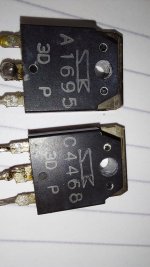
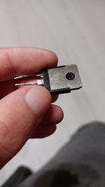
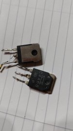
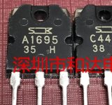
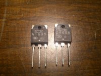
@amplidude How do they look to you? Bavk is very shiny phone camera can't really pick that up .
PS: don't mind the ulgy legs, one of them broke because gravity is a b....
Long story short it was attached to a heatsink that met the ground at some point. Me being a fool .
I have 8 of them from that amp. 4pnp 4 npn, maybe I'll use 4 per channel. Rise the voltage to +- 45.
PS: don't mind the ulgy legs, one of them broke because gravity is a b....
Long story short it was attached to a heatsink that met the ground at some point. Me being a fool .
I have 8 of them from that amp. 4pnp 4 npn, maybe I'll use 4 per channel. Rise the voltage to +- 45.
Attachments

Last edited:
I'm not sure bruno, my first thought is theire genuine, can you google and find pic of a true genuine, perhaps a photo of one cracked open, the innards don't lie.
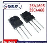
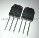
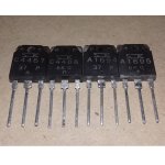
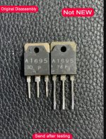
@amplidude these are from old , salvaged. first 3 photos. and the rest are from aliexperess, alibaba, other " new batch " fake probably, they look different, they have a " square " where the name is printed.
I couldn't find a cracked photo.
I couldn't find a cracked photo.
Attachments
There is a thread specifically for people wanting to verify their transistors, I cannot tell you with any certainty which are kosher.
Oh by the way, I recently learned that film capacitors have a proper direction in circuits,
Let's take the input cap which in my case is k73-16, I hooked it up the my oscilloscope, turned volt per division to 5mv, hooked the capacitor to probe and ground crocodile, while holding it in my hands, first reading gave 50hz cycle and 15mv, next I flipped probe ends and got only 5mv reading, that a tad over 9db noise reduction, reason is that the outerlayer foil is grounded, shielding the inner turns, so in circuits where low noise matters always test the film cap, note the end with lowest reading and place it in circuit with the lowest impedance.
Could be interesting building two identical monoblock amps or pre, one with correct direction, one with opposite, and see which numbers they yield.

Oh noooo! Now I have to check hundreds of them mounted with a random direction 🤣Oh by the way, I recently learned that film capacitors have a proper direction in circuits,
Old days manufacturers placed a vertical line where the external pin connection.
I wonder why we don't see those markings anymore, jacques, yes we have busy times ahead..😉
But I must say I was surprised about the 9db difference.
But I must say I was surprised about the 9db difference.
What if you wrap the whole cap in aluminium tape, ground it , and try again, does it perform the same after this, no matter if you switch the " polarity " ?Oh by the way, I recently learned that film capacitors have a proper direction in circuits,
Let's take the input cap which in my case is k73-16, I hooked it up the my oscilloscope, turned volt per division to 5mv, hooked the capacitor to probe and ground crocodile, while holding it in my hands, first reading gave 50hz cycle and 15mv, next I flipped probe ends and got only 5mv reading, that a tad over 9db noise reduction, reason is that the outerlayer foil is grounded, shielding the inner turns, so in circuits where low noise matters always test the film cap, note the end with lowest reading and place it in circuit with the lowest impedance.
Could be interesting building two identical monoblock amps or pre, one with correct direction, one with opposite, and see which numbers they yield.
I actually today have grinded some copper foil I had laying from a old inductor, will attempt to do what you proposed and see readings.
Good, Im curious. but , I googled your cap, looks like it has aluminium around it, is it connected to any of the two wires?. Im sure it is since you said if you wire it in different " polarity " it " acts " better. " But I must say I was surprised about the 9db difference." . and if it is you can not ground it. " over 9db noise reduction, reason is that the outerlayer foil is grounded, shielding the inner turns, " .I actually today have grinded some copper foil I had laying from a old inductor, will attempt to do what you proposed and see readings.
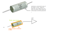
I was thinking something like this ( picture down bellow ).
Also , english is not my native langauge, sorry for mistakes, I hope I'm getting understood.
- What I was thinking, let's say a film cap that is plastic on the outside, if you wrap it in some kind of foil, aluminum , copper does not matter, and connect it to GND ( not attached to any of the cap leads ) , would you still see the improvements you saw with your capacitor connected in the " correct " way ?.
Attachments
You're right but I checked, the metal chassis read megaohms on both pins, totally detached, will try copper foil tomorrow and check in here. Off to bed..
So I made this capacitor copper condom on a roederstein mkt 1813 10uf.
Without condom and outer foil connected too scilloscope gnd it picked up 10mv noise,
With this steampunk condom, oscilloscope could not pick up any signal
With lowest setting, 5mv pr division, and it did so in either direction.
I will use this in my p3a it seems logical.
Had it been a gauss band jaques would have mumified himself in foil..🙂
Last edited:
Very interesting. So this obviously this indicates that bigger isn't always better, the bigger the area, the more noise pickup 🙂
Mr Carlson has an old video discussing cap orientation and describes a tester he designed....in case you are interested.
He is never short of a tektronixs scope or two!
He is never short of a tektronixs scope or two!
here are a few measurements, all done with 8 ohm load all 2.83 volt rms .
1, frequency response, 3db down at circa 180khz.
2. 1khz squre wave
3. 10khz square wave
4. 20khz square wave
5. amplifier noise, shorted input 8r load.
By the looks of it the generator seems to be struggling, a bit of overshoot.
Response is ruler flat from 10hz to 20k, and further.
Input capacitor is a very big dc link capacitor 200uf, just lying on table with cables crossing, doesn't seem to pick up much noise according to last photo.
ps. green trace is amp, yellow generator


 View attachment p3a noise shorted input 8r load.png
1, frequency response, 3db down at circa 180khz.
2. 1khz squre wave
3. 10khz square wave
4. 20khz square wave
5. amplifier noise, shorted input 8r load.
By the looks of it the generator seems to be struggling, a bit of overshoot.
Response is ruler flat from 10hz to 20k, and further.
Input capacitor is a very big dc link capacitor 200uf, just lying on table with cables crossing, doesn't seem to pick up much noise according to last photo.
ps. green trace is amp, yellow generator
Last edited:
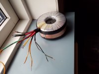
Found this nifty transformer the other day, it's perfect for my p3a, 4 single tap with 22 volts, and 2 with 17 volt for speaker protection, it was somewhat beaten up, so nursed it a bit, it got a gauss belly band, now I can do dual rectifiers for left and right, btw , it's a 500w toroid, no buzz.
Attachments
- Home
- Amplifiers
- Solid State
- P3A Comparison table ( long .... )