For me the heart of the design is the bootstrapped voltage amplifier, and of course Rod's compound pair output stage. I've found that the best performance gain comes from simply substituting a better VAS transistor, reducing the miller cap and adding a phase lead.
Small input degeneration resistors seem to add some small refinement to the sound, without changing the sonic signature. This was most apparent when tested with the low noise & high gain BC550C LTP transistors shown. The added advantage of these degen resistors is that it make it trivial to balance the collectors by fine-tuning R4. I've tried adding a current mirror (with and without degeneration) - no difference in sound.
I like your design. It should have high slew rate.
May be you can try different value of bootstrap resistors. 😎
Thanks bimo, I've never simmed this schematic, but I should imagine it slews pretty well with the relatively high tail current and low Cdom. I wouldn't say its my design - its pretty much Rod's circuit with careful choice of components and a few tweaks here and there.
I have played around with the bootstrap resistors. Rod's values work well and the VAS transistor remains cool enough that a heatsink it not needed for 35V rails.
I have played around with the bootstrap resistors. Rod's values work well and the VAS transistor remains cool enough that a heatsink it not needed for 35V rails.
Thanks bimo, I've never simmed this schematic, but I should imagine it slews pretty well with the relatively high tail current and low Cdom. I wouldn't say its my design - its pretty much Rod's circuit with careful choice of components and a few tweaks here and there.
I have played around with the bootstrap resistors. Rod's values work well and the VAS transistor remains cool enough that a heatsink it not needed for 35V rails.
I mean different value of both bootstrap resistor. Example: 2K7 and 3K9, etc. with same VAS current.
Yes I've tried that too. Sound is best when R11 = 3k9 and R12 = 2k7 ;-)
Thank you, Ranchu. It confirm that THD profile is affect the sound.
Yes I've tried that too. Sound is best when R11 = 3k9 and R12 = 2k7 ;-)
Hi Ranchu32,
Could you identify which is R11 and R12 of the two Vas collector load resistors please as they don't match the references in your schematic of post 620 (shown as R10 & R11). Thanks.
Hi Ranchu32,
Could you identify which is R11 and R12 of the two Vas collector load resistors please as they don't match the references in your schematic of post 620 (shown as R10 & R11). Thanks.
Apologies - my mistake.
R10 and R11 would be 2k7 and 3k9, respectively. I will post an updated schematic sometime later tonight or tomorrow.
I am not sure that this is the right place to do that I actually think that it will be better to create some new thread regarding your work .
As described in the first place the idea here is to discuss the P3A in comparison with other amplifiers but also in a basis that the schematic remains original .
Thank you
Kind regards
Sakis
As described in the first place the idea here is to discuss the P3A in comparison with other amplifiers but also in a basis that the schematic remains original .
Thank you
Kind regards
Sakis
Hi Ranchu,
I will follow over to your new Thread.
I too like your new version.
There are a couple of little tweaks I would add. Maybe I should build one and test them.
I will follow over to your new Thread.
I too like your new version.
There are a couple of little tweaks I would add. Maybe I should build one and test them.
Thanks guys for starting a fresh thread. As much as I am enjoying the progress of Ranchu's build, the main reason I've subscribed to this thread is that I find Sakis's posts about his repairs and comparisons to Rods amp so very interesting.
Yes - totally agree.I find Sakis's posts about his repairs and comparisons to Rods amp so very interesting.
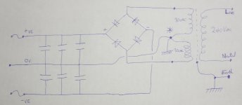
The silicon does seem to be a better idea as opposed to hot glue so I'll go with that, and I'll keep the filter caps simply as is for now and make them CRCRC at a later date.
This is the layout I'll use which will feed both channels,- initially.
Now, do I connect the * point to the chassis or don't I? I guess I'll try both ways and check for hum.
Kind Regards
Roy.
Attachments
Last edited:
It seems funny continuing with another build here in the comparison thread if you agree with Kimbo's post. Anyways, why not use ESP's recommended design PSU, P04? It adds a ground lift circuit to reduce the likelihood of hum with DIY builds.
Power Supply for Power Amplifiers
Power Supply for Power Amplifiers
Royv,
it is much more important to keep the loop area of the secondary to first pair of smoothing caps as small as possible.
Similarly you must keep the loop area of the primary cabling as small as possible.
Once that is achieved, look to see how you can make the audio ground to Chassis connection, without disturbing the low loop area of the charging circuit.
You can adopt the Disconnecting Network (DN), but save that until you have tested the build without a Chassis.
Only assemble inside the Chassis after you have worked out how to fold the linear bench top layout into a package that fits the case and then tested it on the bench in that folded shape.
When you finally get to add the safety connection using the DN, add the optional switch in parallel to the other paralleled DN components.
Switch closed =direct connection
Switch open = DN in chassis connection.
test it using a temporary DN.
You may find that the direct connection works quietly.
If this is the case, then the temporary DN goes back on the shelf ready to test the next build.
Further to the above.
Some British separates manufacturers brought out speaker terminals that were shrouded in plastic insulating material and eliminated the "hole" into which an inquisitive child could poke a metal object. This special connector is disliked and fairly universally NOT adopted outside Britain.
It is a safety measure to protect our children from an obvious danger.
Why did we need this in Britain?
Because the speaker terminals are usually exposed conductive parts.
And the rule IS that they MUST be connected to Chassis.
The solution: make them NOT EXPOSED.
Why is the rest of the world ignoring this safety requirement?
I am surprised that diy-ers do not use Neutrik Speakon connectors which have all the safety measures built in, are purpose made for loudspeaker outputs and are available in many countries, unlike BFA loudspeaker connectors that are available only in Britain.
No........................unlike BFA loudspeaker connectors that are available only in Britain.
Many are made in the Far East and that can only be profitable if they are making millions for use in many other regions than just a few audio separates sold only in Britain.
There is actually a number of reasons :
Neutrik Speakon is capable of plenty of Watts if used in PRO set ups but obviously cannot handle 30audiophile watts
Neutrik Speakon cables may be 4 times 2.5mm or a bit more which is also enough for plenty of 2 way watts but still cannot handle 30 audiophile watts
Neutrik Speakon may not accommodate hi end cables ....
Neutrik Speakon do not offer the option to short circuit your cables bad bad ..too bad but banana plugs with audiophile cables do !!!
Neutrik Speakon do onot offer the option of reversed polarity if once connected right But again banana plugs do !!
Yet again the exposed parts ( like banana plugs from a speaker ) are not a subject to a potential danger at least according to existing regulations that might change in the feature so banana plugs are still fine ... Neutrik Speakon though have everything made safe .
In no other electric or audio configuration any plug that carry "hot" or outgoing power or signal has a male gender orientation.... Only speaker banana plugs and RCA plugs ...
As a result HIFI suffers from a number of kid decease and protocols established many many years ago and should be altered to a better system ..
Kind regards
Sakis
oh and by the way
As we speak and before CE times the Japanese protocols regarding speaker cables where far more different than European or US .
If you see how the wiring was( inside amplifiers ) done often having speaker cables tied up together with power cables in a way and proximity that now days is totally unacceptable .
On the other hand if you look at the old QUAD not only speaker cables with unacceptable 230 wiring but also signal cables and BCE cables was tied up all together just because that looks neat Problem is that the English knew and choose to ignore as a general rule of established arrogance ...
Happy regards
Sakis
Last edited:
- Home
- Amplifiers
- Solid State
- P3A Comparison table ( long .... )