Ok the 2nd harmonic will not be being masked but third harmonic and higher certainly will be being masked by the sound cards inherent distortion I'd say. You might want to try at maybe -6 to -10db input level to the sound card. And see how it looks.
Tony
Tony
I finally think I have figured out how to use the Focusrite 2i2 2nd gen and ARTA.
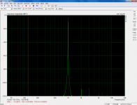
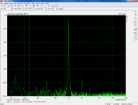
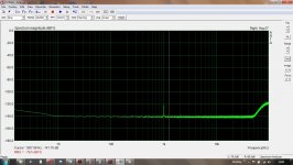
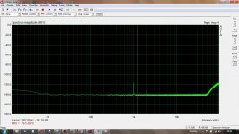
Below left see the loopback shot and on right the adjusted H2 shot of the BA3. I had matched Idss Jfets and curve traced matched Mosfets and I thought the middle position was right. But I was very wrong. Had to turn several turns before H2 nulled out and then I reintroduced it in phase as Nelson has suggested.
nash
Attachments
Pass DIY Addict
Joined 2000
Paid Member
Tony - as I reduce the volume level, the 2H peak disappears. I'll run it again at 6-10dB below the 0dB ref point to see what I get...
Nashbap - your image is close to what I am seeing, but it takes near-maximum volume in my BA-3 to see it. What is your volume level setting in the second image you've posted?
Nashbap - your image is close to what I am seeing, but it takes near-maximum volume in my BA-3 to see it. What is your volume level setting in the second image you've posted?
Hi Eric. Try with the loopback. If the HD improves there then you have a better base level. What you then need to do is try to get the original level going into the amp and attenuate on the output of the amp if you know what I mean.
I'm not sure of your setup, but if you have attenuation after the sound card into the amp, and attenuation after the amp going into the sound card, then once you have the output level on the loopback that gives best results, try and keep that level and adjust the pre and post amp controls to get what you want, but keeping the actual arta level constant.
Hope that made sense!
Tony.
Nashbap - your image is close to what I am seeing, but it takes near-maximum volume in my BA-3 to see it. What is your volume level setting in the second image you've posted?[/QUOTE]
To get -3db I set the Focusrite output monitor knob about 3/4 and then wherever the preamp attenuator comes close to -3db. With the 2i2 it is very easy, just turn the output untill you get the desired -3db. It will depend on what ACV your soundcard is outputting.
nash
To get -3db I set the Focusrite output monitor knob about 3/4 and then wherever the preamp attenuator comes close to -3db. With the 2i2 it is very easy, just turn the output untill you get the desired -3db. It will depend on what ACV your soundcard is outputting.
nash
I'm wondering if any one has any pointers on how to discern the phase of the distortion from the sound card method?
I think when adjusting with the spectrum analyzer (sound card + software) one would need to look at the voltages at the source resistors (R3, R4 I think) to determine whether H2 is in phase or out of phase with the fundamental.
This explanation seems to make sense:
Just going off memory at the moment and logical reasoning: As the source resistor on 2sk170 approaches zero the 2nd harmonic will be in phase with the fundamental. As the source resistor connected to 2sj74 approaches zero the 2nd harmonic will go out of phase with the fundamental.
Dennis, you have the perfect tools to verify this (distortion analyzer + scope).
I think when adjusting with the spectrum analyzer (sound card + software) one would need to look at the voltages at the source resistors (R3, R4 I think) to determine whether H2 is in phase or out of phase with the fundamental.
This explanation seems to make sense:
Dennis, you have the perfect tools to verify this (distortion analyzer + scope).
Having recently set H2 on my F5Tv3 using ARTA and the 2i2, once you reach the lowest point for H2 which also happened to be the lowest THD indicated, turning P3 in the direction where R3 decreases is setting in phase, conversely as R3 increases H2 is out of phase. I listened to a piano trio and the inphase H2 made the piano sound correctly positioned while the exact same amount of H2 out of phase made the piano move a bit forward. I preferred the in phase setting. As suggested I hope someone can verify this for our better understanding.
nash
Hi Radule,
Once I get my soundcard setup working, I'll have to try out Diana and see how
the distortion waveform compares with that from the HP.
Thanks,
Dennis
Once I get my soundcard setup working, I'll have to try out Diana and see how
the distortion waveform compares with that from the HP.
Thanks,
Dennis
Couldn't be happier with the way this thread is fleshing out the 212 and the adjustment of P3. Should be ordering my 212 Friday.
Russellc
Russellc
Having recently set H2 on my F5Tv3 using ARTA and the 2i2, once you reach the lowest point for H2 which also happened to be the lowest THD indicated, turning P3 in the direction where R3 decreases is setting in phase, conversely as R3 increases H2 is out of phase. I listened to a piano trio and the inphase H2 made the piano sound correctly positioned while the exact same amount of H2 out of phase made the piano move a bit forward. I preferred the in phase setting. As suggested I hope someone can verify this for our better understanding.
nash
This may become a little more apparent once I start playing with my own 212, but not sure what you mean by:
"turning P3 in the direction where R3 decreases is setting in phase, conversely as R3 increases H2 is out of phase"
A little confused about R3 increasing and decreasing...some measurement across R3?
Russellc
P3 increasing and decreasing, CW & CCW?
There seem to be a number of free downloads for 'PC scope', just downloaded this one Download looks like it works, haven't sent a signal to it yet.
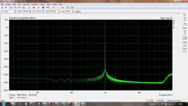
Been playing with the 2i2, just checking baselines, balanced input DRV134 2 Channel DRV134 Unbalanced to Balanced Converter Board Match Input Amplifier | eBay (it's cheaper to buy than make) I put a ground wire breaker in the output lead, not a lot of difference with and without, slightly quieter with; haven't done any unbalanced baselines yet.
Forgot to mention, generator set to 0dB, output level measured at 500mV, no gain on the input.
I can't remember if we from 6L6 video can determine in which direction from P3 center the 2nd harmonic is "in phase"?
If we just know that and we start adjusting P3 from center position it should be fine just to use the "sound card method"?
There seem to be a number of free downloads for 'PC scope', just downloaded this one Download looks like it works, haven't sent a signal to it yet.
Been playing with the 2i2, just checking baselines, balanced input DRV134 2 Channel DRV134 Unbalanced to Balanced Converter Board Match Input Amplifier | eBay (it's cheaper to buy than make) I put a ground wire breaker in the output lead, not a lot of difference with and without, slightly quieter with; haven't done any unbalanced baselines yet.
Forgot to mention, generator set to 0dB, output level measured at 500mV, no gain on the input.
Attachments
Last edited:
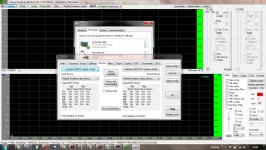
The noise floor looks much better than I would have expected from the drv134. I ruled them out from the datasheet spec of 98db noise floor. However your level in the screen shot seems to be -40 db so perhaps that explains it. Can you get close to 0db on the signal and still get -140db?
Tony.
Tony.
Having recently set H2 on my F5Tv3 using ARTA and the 2i2, once you reach the lowest point for H2 which also happened to be the lowest THD indicated, turning P3 in the direction where R3 decreases is setting in phase, conversely as R3 increases H2 is out of phase. I listened to a piano trio and the inphase H2 made the piano sound correctly positioned while the exact same amount of H2 out of phase made the piano move a bit forward. I preferred the in phase setting. As suggested I hope someone can verify this for our better understanding.
Thanks Nash, that was most helpful!
Just now I was playing with H2 while monitoring R3 and R4. R4 doesn't move with the adjustment of P3, but sure enough R3 does. H2 cycles from a high point to null and back high again as R3 continuously drops.
My jfets were a tightly matched quad. This must explain why adjusting for consistant H2 between channels also result in the same voltage (32mVDC in my case) on R3 for both left and right channel.
Very cool!
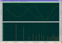
I installed Diana few days ago and for 2nd harmonic phase jobs its working.
Wait a minute...who's this DiAna🙂
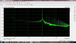
Can you get close to 0db on the signal and still get -140db?.
No, one for the bin.
Attachments
Crap....I knew someone was going ask that. I don’t remember, and I didn’t write it down. Sorry.
No, one for the bin.
Your not clipping the input there are you, that looks a lot over 0db! Try at say -3db 🙂
Tony.
This may become a little more apparent once I start playing with my own 212, but not sure what you mean by:
"turning P3 in the direction where R3 decreases is setting in phase, conversely as R3 increases H2 is out of phase"
A little confused about R3 increasing and decreasing...some measurement across R3?
Russellc
You will see in the circuit that the the two halves (50r and 50r) of the 100r pot P3 are in parallel with R3 andR4 when P3 is in the middle position. If you measure across R3 and R4 they will each read 8.3r. Now if you turn P3 in a certain direction so that the leg in parallel to R3 is say 25r and the other leg parallel to R4 is 75r then R3 will read 7.14r and R4 will read 8.83r. As I turned P3 so that R3 was decreasing H2 started decreasing, then H2 reached its lowest value(most negative) and then as I turned P3 further in the same direction H2 started increasing while R3 decreased even further.
nash
nash
- Home
- Amplifiers
- Pass Labs
- P3 Adjustment for the average Hobbyist