Hello Zsolt,I can use it directly on the chip output, as whit the 9038q2m?
Yes, looks similar to 38q2m.
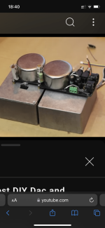
For sale. $500. Active version of SE I/V board based on D60 1:18 trafos + buffer on the matched 2sk170V/2SJ74V jfet pairs. Stackable on to iancanada's DAC, but suitable with any other current output type DACs (TDA1541, PCM63, AD1865, etc...). Needs from +/- 12V to +/- 20V for operating (+/- 30mA).


You should change prices in first post, seeing they changed.
Also noticed the link is miss spelled, doesn't take you to your website. https://ivxformers.com/
Also noticed the link is miss spelled, doesn't take you to your website. https://ivxformers.com/
Last edited:
Changed. Thanks🙏You should change prices in first post, seeing they changed.
Oops 😛You should change prices in first post, seeing they changed.
Also noticed the link is miss spelled, doesn't take you to your website. https://ivxformers.com/
Fixed! Thank you again!
Question pls is there a capacitor along the signal line ? ThksFor sale. $500. Active version of SE I/V board based on D60 1:18 trafos + buffer on the matched 2sk170V/2SJ74V jfet pairs. Stackable on to iancanada's DAC, but suitable with any other current output type DACs (TDA1541, PCM63, AD1865, etc...). Needs from +/- 12V to +/- 20V for operating (+/- 30mA).
View attachment 1336580
Here is again the yesterday recoding of my system. Between the DAC chip (PCM63) and amplifier there are 4! (FOUR) D60 step-up transformers 😛
Hello,
Yes, the iv output board based on my D60 trafos is available. Cost is $650 including ww delivery (national post).
Ivan.
Yes, the iv output board based on my D60 trafos is available. Cost is $650 including ww delivery (national post).
Ivan.
It is a bit different and looks like this now

It is possible to make on the previous PCB style if needed
It is possible to make on the previous PCB style if needed
Hi Ivan, I wonder if there is an easy way (not taking off the soldered Jfets) to change the active mode to passive mode for your new PCB? Thanks!
Hi.Hi Ivan, I wonder if there is an easy way (not taking off the soldered Jfets) to change the active mode to passive mode for your new PCB? Thanks!
Sure. There are two separate terminals for active and passive outputs. To use passive output simply do not apply PSUs for the active stage. Jfets are simply in parallel with the passive outputs (jfets input impedance is huge).
Thank you! That's great, I would like to try something alternative to Jfets here, lol.Hi.
Sure. There are two separate terminals for active and passive outputs. To use passive output simply do not apply PSUs for the active stage. Jfets are simply in parallel with the passive outputs (jfets input impedance is huge).
BTW, how much DC the transformers can handle? I just built a 1541A board with DC offset (no capacitors at the output), it can have 2V+ DC when it gets powered on for a few seconds. Is it safe to use D60 here or some extra protection is needed... (sorry if I asked stupid questions here, have very limited knowledge and could worry about something nonsense)..
- Home
- Vendor's Bazaar
- Output transformers for DACs