I am surprised that very little is said about contact protection design.
Contact rating gives the max voltage and current they can handle feeding a resistive load. There will be some arcing on make and brake and the contact will operated under these conditions for a time equal to its rated electrical life.
If adequate contact protection is added the rating is totally different.
In our case, the problem is only on brake because it is easy to mute the amp before switching on ( make).
There are two types of arcs happening:
one is called glow discharge and happens above 300 volts. It is related to the ionization of air. This is avoided by clamping the output of the amplifier to Vcc
the inductive spike will then never reach 300V.
The other one is metallic arcing and is due to high speed electrons vaporizing locally the anode or cathode and creating a molted bridge. If less than a certain voltage ( minimum arcing voltage) or a certain current ( minimum arcing current) the arc will stop. These values are low : between 10 and 18 volts depending on material and 400 and 800 mA. These values are much lower if contacts are damaged. These low values shows why contact arcing is difficult to avoid.
To avoid the starting of the arc, the voltage gradient between electrodes should remain below 0.5Mvolts/cm. With typical speeds of opening a requirement to avoid any arc can be found:
Keep the initial rate of rise of contact voltage under 1V/microsec.
If we put a capacitor in // with the contact, the initial rate is I / C where I is the load current to be switched. The design rule is then C> I x 10 exp(-6)
or take a capacitor whose value in micro farads is higher than the value of the load current in amps.
Because on make the amp is muted, the capacitor is empty and doesn't need a classical protection serial resistor which always induces some arcing on brake.
If we can avoid any arcing a question remains: what about the building up of a oxyde layer in time?
A lot more can be found in H. Ott classical book;
Hope this helps
JP
An ar
AFAIK, solid state relays do affect the quality of the output signal. That has been reported by many users. SCR protection also does.
As output protection is a necessary evil, it looks like a regular relay might be the lesser one. Isn't it?
I don't think so.
Modern Trench mosfets feature very low terminal to terminal capacitances and switch very fast (latest devices can switch in 2-3ns - its the drive circuit that limits switching speed in most cases). The low Rdson means 2 back to back devices at 150V Vds rating can be under 15mO. This is very good.
JPV, you raise some good points. But, the issue is how do you break 75V at 20A (fault condition on a big amp). This spec is way outside any reasonable cost relay. Further, at these levels, the life of a relay is very limited, and it can only break high powers a few times before it needs replacing.
Relays are good - but there are no reasonably priced ones that will do a good job on the output of a big amplifer when it suffers a catastrophic fault. Better to chose a crowbar or a mosfet SSR solution.
Relays are good - but there are no reasonably priced ones that will do a good job on the output of a big amplifer when it suffers a catastrophic fault. Better to chose a crowbar or a mosfet SSR solution.
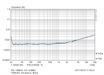
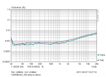
Attached pictures are showing real "degradation", two lines in each picture , measuring before and behind SSR.AFAIK, solid state relays do affect the quality of the output signal. That has been reported by many users. SCR protection also does.
Attachments
Last edited:
IRLB4030About 1ppm at 20KHz.
What mosfets were you using out of interest?
JPV, you raise some good points. But, the issue is how do you break 75V at 20A (fault condition on a big amp). This spec is way outside any reasonable cost relay. Further, at these levels, the life of a relay is very limited, and it can only break high powers a few times before it needs replacing.
Relays are good - but there are no reasonably priced ones that will do a good job on the output of a big amplifer when it suffers a catastrophic fault. Better to chose a crowbar or a mosfet SSR solution.
I thought I explained that the specs you are mentionning are for relays without contact protection.
For your example, put a capacitor of 30 microfarads in // with the contact and rated at 150V you may then use a contact that passes the 20A which is common and not one that breaks 20A under 75V. There will be no arc.
The point is that if you do not allow the arc to start by keeping the voltage gradient under 0.5Mvolts/cm when the contacts open then there will be no arc . If an arc starts, then the available current will pass through the arc and degrade or molt it. Of course you need a non polar capacitor that can take this inrush current..
jp
I have put my thoughts on SSR's on my website here Audio Amplifier Design and Circuits | hifisonix.com - its the first .pdf at the top of the page.
Elegant approach, but dangerous, the speaker cable/connectors can be at 70volts or even at 60 volts of music! Adding a relay on the hot side that switches at the same time as the FET switch will help this and the offness.
I thought I explained that the specs you are mentionning are for relays without contact protection.
For your example, put a capacitor of 30 microfarads in // with the contact and rated at 150V you may then use a contact that passes the 20A which is common and not one that breaks 20A under 75V. There will be no arc.
The point is that if you do not allow the arc to start by keeping the voltage gradient under 0.5Mvolts/cm when the contacts open then there will be no arc . If an arc starts, then the available current will pass through the arc and degrade or molt it. Of course you need a non polar capacitor that can take this inrush current..
jp
If you put a 30uF cap across the relay contacts you will have signal leakage. I presume most designers do not want that. I certainly don't consider that acceptable.
Last edited:
Elegant approach, but dangerous, the speaker cable/connectors can be at 70volts or even at 60 volts of music! Adding a relay on the hot side that switches at the same time as the FET switch will help this and the offness.
No more dangerous than an amplifier that is running at nearly full power, with cables and not connected to a speaker. Where do you stop?
Use the FET switch to make and break the current/voltage, then use a small high quality relay to bypass the FET switch.
If you put a 30uF cap across the relay contacts you will have signal leakage. I presume most designers do not want that. I certainly don't consider that acceptable.
If there is a catastrophic fault leakage is not existing DC;
If the amp is switched off a good design includes the muting of the amp and so no leakage.
Could you explain when do you see a problem.
Thanks
JP
If you put a 30uF cap across the relay contacts you will have signal leakage. I presume most designers do not want that. I certainly don't consider that acceptable.
Also, if for some reason there is any charge on the cap when the relay closes, you need a new relay...
jan
Also, if for some reason there is any charge on the cap when the relay closes, you need a new relay...
jan
If the amp is muted in off state there will be no charge on the cap so no arc from off to on.
If the output is blown (stuck to Vcc) you will need to switch off the power and discharge all the caps before repair;
Where is the problem?
JP
Use the FET switch to make and break the current/voltage, then use a small high quality relay to bypass the FET switch.
If you brake, you will need to open the high quality relay first then the FET. The delay induced by the DC detect circuit is I suppose longer than the delay of the relay. In any case, the full potential speed of a FET switch is wasted.
Is it a problem ?
JP
I believe any good power relay can well afford to discharge 30 uF (microFarad)sometimes.Also, if for some reason there is any charge on the cap when the relay closes, you need a new relay...
jan
If you really want you can parallel it with 10kOhm, the you have a discharge time constant of 0.3 s.
Of course then you do not have insulation on DC as well. But I presume the goal is limitation (i.e. protection) not insulation.
No more dangerous than an amplifier that is running at nearly full power, with cables and not connected to a speaker. Where do you stop?
Amps at full volume are rare, but when a fault occurs putting the full rail voltage on the speaker lines and some one wants to check the connections, ZAP. Sorry but if theres the slightest chance (and there is) that your circuit could kill someone it probably will so it shouldnt be on this forum. Add something to kill the hot side or risk getting sued.
I believe any good power relay can well afford to discharge 30 uF (microFarad)sometimes.
If you really want you can parallel it with 10kOhm, the you have a discharge time constant of 0.3 s.
Of course then you do not have insulation on DC as well. But I presume the goal is limitation (i.e. protection) not insulation.
The classical solution is to put a serie resistor with the protection capacitor. The drawback of this solution is that on brake there will be some initial arcing due to the voltage drop on the resistor.
If before switch on the amplifier is muted the capacitor will be fully discharged and the contact will see no inrush current so no spike;
JP
The MOSFET relay switch on my website below is designed to act as a speaker mute switch for anti switch on thump, and to provide a reliable switch under catastrophic amplifier failure. My experience in this regard is what started this thread off.
Wrt safety, you can always add a normal relay in series with the hot speaker terminal in the conventional way. However, this does not solve the very real example problem outlined above (amp on and playing music but speaker wires not connected to anything). The only way to solve this would be to measure the load and if open, disengage the output. I leave it up to you to decide how to handle these situations.
Wrt safety, you can always add a normal relay in series with the hot speaker terminal in the conventional way. However, this does not solve the very real example problem outlined above (amp on and playing music but speaker wires not connected to anything). The only way to solve this would be to measure the load and if open, disengage the output. I leave it up to you to decide how to handle these situations.
- Home
- Amplifiers
- Solid State
- Output Relays