Tip: Switch the speaker ground return line and ditch the opto.
The amplifier is designed for bridged usage, switching the ground connection is not possible. Why ditch the opto. I am going to use an FOD3120 and thus will have a very simple circuit (no need for the two transistors, and even faster). At a price of about 1.30 Euro's, how would you beat that (price or performance wise)?
Naturally it would be possible to drive the NMos fet's with an very simple circuit (almost non) if you were switching ground.
Even if you are switching a bridged amp,you can ditch opto.
Separatley, I am still trying to understand why you want 4 mosfets in parallel when 1 will do the job better thaany currently available relay.
Separatley, I am still trying to understand why you want 4 mosfets in parallel when 1 will do the job better thaany currently available relay.
Even if you are switching a bridged amp,you can ditch opto.
Separatley, I am still trying to understand why you want 4 mosfets in parallel when 1 will do the job better thaany currently available relay.
First of all, I did decide to go with 4 NMos devices. 4 x IRFP4668PBF for Rdson around 10 mOhm (Mouser 3.85 Euro/100) http://www.irf.com/product-info/datasheets/data/irfp4668pbf.pdf
They are 2 by 2 series and parallel giving about 10 mOhm. NMos devices with sufficiently low Rdson and Vds of 200 Volts are not easy to find. When using 10 mOhm devices 2 in series (non parallel) I would get 20 mOhm, and that is about the same as an conventional (good quality) relay (and I want to do better than that in all respects). The other thing is, it is cheap, compared to a good quality relay. I could be using 10 in parallel (for a total of 20) and not even approach the price of a good relay, so why not? Why not improve 'ALL' specs of the mechanical relay, be faster, be more reliable and have a lower Ron!
And I am interested in that non-opto solution 🙂 just out of curiosity.
I want to ditch opto requirement.
Can you show me the light?
Unless I'm missing something it's easy because the FET's are ground referenced.
It's just a variation of this,
http://www.diyaudio.com/forums/solid-state/191449-output-relays-12.html#post2655631
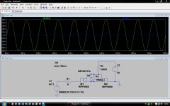
Which seems to work OK as shown here. First pic is switch on. Blue trace is voltage on R/H end of 8 ohm load... zero volts.
Attachments
Unless I'm missing something it's easy because the FET's are ground referenced.
It's just a variation of this,
http://www.diyaudio.com/forums/solid-state/191449-output-relays-12.html#post2655631
Which seems to work OK as shown here. First pic is switch on. Blue trace is voltage on R/H end of 8 ohm load... zero volts.
But, as I noted, this (referenced to ground) will not work for bridged amplifiers.
You might be able to move it into the negative supply rail on a bridge amplifier, just a single FET should be OK. The circuit would need a change of origin for detecting DC off-set and removing the FET drive.
Mooly has it. But I used a slightly more complex drive circuit. I will post something up later today if I remember. For a bridge amp, you would have to reference accross both the supply rails.
But, as I noted, this (referenced to ground) will not work for bridged amplifiers.
So you move your reference point.
Mooly has it. But I used a slightly more complex drive circuit. I will post something up later today if I remember. For a bridge amp, you would have to reference accross both the supply rails.
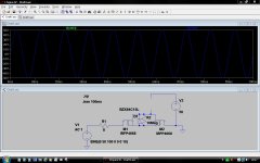
Yes, and in the example here which seems to work OK you need to be able drive the fet gates to higher than the positive rail. Or more correctly to maintain at least the Vgs required to keep the FET on. I left the drive at plus 50 volts to show the "clipping" that occurs if you don't. Change V3 to 55 volts and the clipping goes. In practice it's easy to arrange a sub PSU rail with a voltage doubler to get a higher rail.
Green trace is V2
Blue trace is other end of 8 ohm load
In the second pic the blue trace is overlaid on the green showing no voltage across 8 ohm.
Attachments
So you move your reference point.
Yes, and in the example here which seems to work OK you need to be able drive the fet gates to higher than the positive rail. Or more correctly to maintain at least the Vgs required to keep the FET on. I left the drive at plus 50 volts to show the "clipping" that occurs if you don't. Change V3 to 55 volts and the clipping goes. In practice it's easy to arrange a sub PSU rail with a voltage doubler to get a higher rail.
Green trace is V2
Blue trace is other end of 8 ohm load
In the second pic the blue trace is overlaid on the green showing no voltage across 8 ohm.
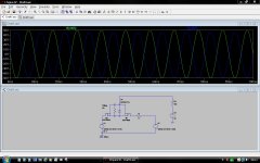
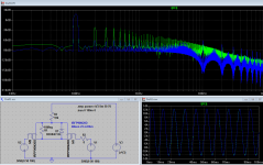
That is not going to work, have a look at the green line in the FFT plot (that is V3 at 50 Volts) if we use 70 Volts then it is way better (blue line) but we need an extra power supply (just to drop the opto).
P.s. you can also see (blue plot) what 46 mOhm is doing, not a pretty sight, we need to get at the least 10 times better to be acceptable (5 mOhm?).
P.s. It also gets worst in real life, my amplifier will be running from +/- 80 Volts and it will be used to drive a ‘Carver Amazing Platinum edition’ magneto static dipole, this has a rated impedance of 4 Ohms. Under the same conditions that will be current (worst case) over 30 Amp’s (at 80 Volts).
Attachments
Last edited:
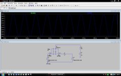
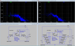
Here a few more FFT's, left side for 2 devices (46 mOhm) and right side 8 devices (11.5 mOhm). You can see a significant degradation of quality in FFT left (compared are the IR3 and IR4). It would be advisable to get the switch at around 10 mOhm (the FFT shows no significant effects at that level).
Attachments
So you move your reference point.
Yes, and in the example here which seems to work OK you need to be able drive the fet gates to higher than the positive rail. Or more correctly to maintain at least the Vgs required to keep the FET on. I left the drive at plus 50 volts to show the "clipping" that occurs if you don't. Change V3 to 55 volts and the clipping goes. In practice it's easy to arrange a sub PSU rail with a voltage doubler to get a higher rail.
Green trace is V2
Blue trace is other end of 8 ohm load
In the second pic the blue trace is overlaid on the green showing no voltage across 8 ohm.
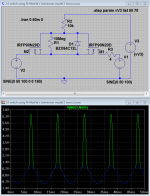
Here is the voltage across the switch, at 50(green) and 70(blue) Volt gate drive (V3).
Attachments
That is not going to work, have a look at the green line in the FFT plot (that is V3 at 50 Volts) if we use 70 Volts then it is way better (blue line) but we need an extra power supply (just to drop the opto)................
It does work 🙂
I cobbled it all together just to try and see if the basic idea was workable for a bridge amp without using an opto and it is.
Your specific requirements are pretty severe current and voltage wise (not that there is any problem with that) and so you do need multiple FET's and to drive them at a high Vgs at all times.
As you say, "but we need an extra power supply (just to drop the opto) ". The voltage doubler I mentioned is easy to implement but ultimately I think the photovoltaic couplers are the most elegant solution for this as they need no level transition from whatever drives them.
O.k. let’s agree on this (although I never would advise cold side switching), you can switch ground when you are sure that you never are gone bridge the amplifier(s).
There will be a penalty (quality wise) when Rdson total is higher than 1/1000’st of the loudspeaker impedance (e.g. with an 8 Ohm loudspeaker you must have a switch with an Rdson below 80 mOhm) (the penalty being at -60 dB).
When using 4 Ohm loudspeakers you need to have a shitch of 40 mOhm (or less), when you bridge these you may want to halve this to 20 mOhms.
Yes you can do without the opto when bridging, but you will need an additional power supply. As the additional power supply will be more expensive than the opto this approach is not advisable (especially (when not using the opto) when you take into account that you need switch the full rail voltage).
I would advise to switch the ‘hot’ side always, you never know when (and who) is going to use the amplifier bridged anyway.
Then there is one more issue, you need to drive the gates fast (very fast) to stay within SOA bounds of these devices (even when using multiple, you need to consider that there is always one that switches last, and thus takes most of the load). For this purpose you need multiple transistors and maybe a bit more, using those opto’s specially designed to drive the NMos devices will free you from these ‘extra’ stuff at an cost of only 1.30 Euro’s or less.
My weapon (device) of choice, to drive the gates, will be the FOD3120. This will give a fast and cheap solution to all obstacles that may (or may not 🙂) be of influence. The floating PSU (2 diodes, 2 resistors, 1 zener and 1 capacitor) will be used to feed it 🙂 See http://www.diyaudio.com/forums/solid-state/191449-output-relays-18.html#post2974843
Last edited:
Can't disagree with most of what you are saying. You have to build to suit your requirements.
Bridged amps aren't really my thing tbh but one thought on this. If the amp is a two channel "stereo" amp that's bridgeable then you have an isolated load when the switches (relays) are open. But you also have two switches in series with the one load. If you are designing a bridged only amp then you can of course use just one switch as in the examples above. I suppose that could be argued against in that the load is always "live" and there could be some fault condition (say a speaker lead rubing against some grounded fixture) that the opening of the switch would not isolate. As with anything you can dream up scenarios where it all falls down.
Ground side switching on a single ended output stage kind of feels wrong but isn't of course. The speaker and witch are just a series circuit. It's an economical and reliable way to do it.
Just to be clear here, it's not the Rdson or the speaker contact resistance that worries me with switching speaker loads. It's what happens under catastrophic amplifier failure events when one of the output devices fails short into a (typically) 4 ohm dc resistance speaker. On a big amp with 75V rails, the current approaches 20A. MOSFET based switches can handle this with ease. Relays can't.
As far as distortion goes, remember its the distortion across a very small signal (mV). It amounts to s few ppm reference the output of the amplifier. No big deal.
As far as distortion goes, remember its the distortion across a very small signal (mV). It amounts to s few ppm reference the output of the amplifier. No big deal.
It's not the current that's the problem, it's the inductive flyback voltage from the reactive load that arcs across the contacts.
Has anyone looked at how this will affect the FETs?
Has anyone looked at how this will affect the FETs?
It's not the current that's the problem, it's the inductive flyback voltage from the reactive load that arcs across the contacts.
Has anyone looked at how this will affect the FETs?
See post 351 http://www.diyaudio.com/forums/solid-state/191449-output-relays-18.html#post2974843, diodes D1...D4 clamp it to the supply rails. The NMos devices need to be able to handle the full supply voltage (and add some margin, say 10%).
Just to be clear here, it's not the Rdson or the speaker contact resistance that worries me with switching speaker loads. It's what happens under catastrophic amplifier failure events when one of the output devices fails short into a (typically) 4 ohm dc resistance speaker. On a big amp with 75V rails, the current approaches 20A. MOSFET based switches can handle this with ease. Relays can't.
As far as distortion goes, remember its the distortion across a very small signal (mV). It amounts to s few ppm reference the output of the amplifier. No big deal.
Or you can have a look at these http://www.diyaudio.com/forums/solid-state/191449-output-relays-19.html#post2977112 When designing/building amplifiers we are trying for the best (THD's at or even below -80 dB), so I would think that it is reasonable to keep the influence of the 'relay' below -60 dB (or less). For this the Rdson must be at 1/1000 of the load impedance. The amount of money involved is very small (in comparison to the transformers, buffer elco's and a decent enclosure), so why not?
- Home
- Amplifiers
- Solid State
- Output Relays