Could somebody please help me understand the circuit path for developing the negative source/ channel voltage in reference to the gate for the circuit in post #288.
I see the positive gate path clearly.
Thanks
I see the positive gate path clearly.
Thanks
Here are (obviously..) internal diodes paralel to Mosfet, so one Mosfet is bypassed by this diode under faulty conditions.As you've got two pass devices though, wired in series, surely under that fault condition each would only see ~half the max voltage or am I missing something?
Could somebody please help me understand the circuit path for developing the negative source/ channel voltage in reference to the gate for the circuit in post #288.
I see the positive gate path clearly.
Thanks
Through MOSFET (and the load). R4 and R5 make voltage divider for Vgs bias.
Last edited:
Member
Joined 2009
Paid Member
A philosophy that has served me well in the past is known to some as "Suck it and see" - (SIAS), meaning that you just wont know how it will go until you actually give it a go.
I have received the parts I ordered. I have cut a pcb to roughly the size I need and I have a space reserved for it in the amplifier chasis (my TGM5 amplifier, which is another thread around here somewhere).
I've attached the 3-channel dc-offset detector circuit and I've used a simple transistor switch to power the photovoltaic couplers, shown in the schematic as LEDs.
The plot shows what happens to the current flow through the LEDs over time (green) and the d.c. signal from the centre channel (blue) which suddenly flips to the rail. Looks like a 30ms long take-down of the output to the speakers after a failure.
Attachments

Member
Joined 2009
Paid Member
Well, after further simulations I see weaknesses and I have updated my design with some key improvements.
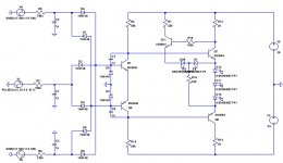
I noticed that when the same dc detect circuit is used to monitor several channels, you can have one channel with dc offset and another channel still singing away with audio. This means that the switching action of the circuit can be impacted by a.f. signals on top of the d.c. - it's not an issue when a channel fails catastrophically but if there is a soft-fail where a small but 'illegal' level of dc-offset occurs the switching can show some 'bounce'. Adding a pair of 'Cdom' caps to the dc-detect devices can address this.
I have also make the solid state relay driving device a symmetrical pair of devices instead of a single. This improves the switching action.
And lastly I wanted to provide for a dual red-green LED indicator, just like on my Bryston amplifier. I added an extra device for this purpose. Now I can run one of those dual LEDs on my front panel. It will glow red when the solid state relay is open, green when it is closed.
Attachments
Hi,
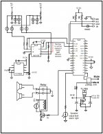
I am also working in a relay system to protect the speaker using a micro. I will use the basic micro Nano series. They are programming in basic and the prices it is a low cost. They are start at 2.98 for a 4 pins output to 28 dollars. I will use the Nano 28 since I have some left over from a project but if I didn't have the extra I will use the. They are easy to programming, It will do job easily and the best thing is that you can tailor it to your needs.
Attached is a the schematic of my design.
Link to Basic micro
Picaxe Alternatives - Nano Microcontrollers.
Attachments
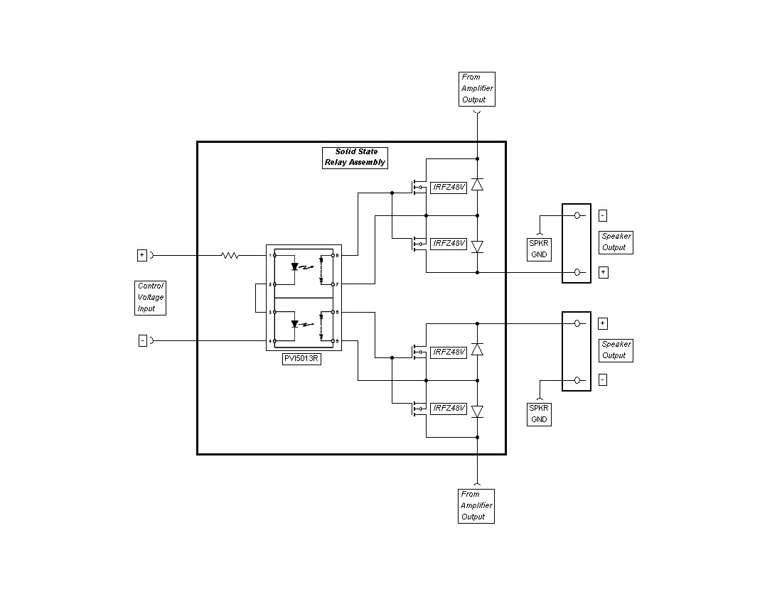
Here's what I use - simple, reliable, easily scalable, and quiet.
I need to replace a failed relay (discussed earlier) and may be sending a Farnell order soon. They only have the PVI5080N in UK stock but this should be suitable in this application?:
PVI5080NPBF - INTERNATIONAL RECTIFIER - RELAY, PHOTOVOLTAIC | Farnell United Kingdom
Any suggestions for MOSFETs? Cheaper the better, I guess the criteria is low RDSon with suitable voltage and current capacity. Perhaps these?:
PSMN017-80PS - NXP - MOSFET,N CH,80V,50A,TO-220AB | Farnell United Kingdom
The coupler should be OK although I liked the Avago (and I see the Avago ones are no longer stocked and out of stock) because being dual the two elements could be run in series to give around 14 to 16 volts gate drive to ensure the FET is absolutely fully on.
In practice 7 to 8 volts should be fine though.
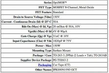
FET looks OK. The RDS is lowish. The IRF2907's I finally settled on had a value of 3.5 mΩ, 75 amp and 75 volt rating. And they are (were) cheap. I felt the 75 volts was good enough because an output failure can only put one rail or the other across the speaker which is ground referenced. It's not like output transistors that can see the full rail to rail swing.
In practice 7 to 8 volts should be fine though.
FET looks OK. The RDS is lowish. The IRF2907's I finally settled on had a value of 3.5 mΩ, 75 amp and 75 volt rating. And they are (were) cheap. I felt the 75 volts was good enough because an output failure can only put one rail or the other across the speaker which is ground referenced. It's not like output transistors that can see the full rail to rail swing.
Member
Joined 2009
Paid Member
I finally built my FET based 'relay' and it is now up and working. As it was installed in an existing amplifier I captured the details in a different thread: http://www.diyaudio.com/forums/soli...imple-symmetric-amplifier-13.html#post2939602
I used the IPB200N15N3 G parts from Infinion, got them from Digikey.
I used the IPB200N15N3 G parts from Infinion, got them from Digikey.
Attachments
Last edited:
After having been looking for suitable mechanical relay’s to be used as a DC protection switch in a high power amplifier, I have to conclude that these are way too expensive for me. The problem is, off course, that the relay will only be used (in anger) a very few times in its life (the amplifier’s life) and in ‘normal’ use it will only switch when the amplifier is idling. So this is a dilemma, get an expensive relay and survive multiple usages, or use a cheap one (like the one from Amplimo (7 Euro’s)) and survive only a few times.
But there is another problem, very decent relays have an ‘on’ resistance of between 30 (the very expensive one’s) and 100 mOhm (the more mundane one’s). Using a 30 mOhm’s relay would just be acceptable, but having a 5 (or less) mOhm relay would be like owning a Rolls Royse. The funny thing is you can own the Rolls Royse and pay for a Volkswagen Polo. That is what I found in this thread.
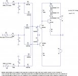
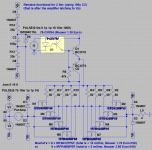
So, thanks to Bonsay (and many other contributions in this thread) ( http://www.diyaudio.com/forums/solid-state/191449-output-relays.html#post2617309 ) this is what I came up with, using the floating power supply, floated by 2 resistors (I think its brilliant Mooly ( http://www.diyaudio.com/forums/solid-state/191449-output-relays-12.html#post2655631 )) gives 15 Volts of power supply. Adding a 100 uF buffer capacitor gives 2 Seconds of ‘hang’-time. Then I added the two transistor gate diver to get switch off times less than 200 uSec, I am sure that will keep the NMos devices within there SOA’s.
Please let me know what you think of this one, you may think it is a bit overdone, but still (I think) the cost is very low, at 10 to 20 Euro it will fit nicely in a large (expensive) amplifier. And compared to mechanical relay’s, of comparable capacity, it is a bargain (those are 100 Euro’s and up). Especially as you consider that you get a 10 or even 5 mOhm’s relay (that is near unobtainium in mechanical relays).
P.s. See also http://www.diyaudio.com/forums/solid-state/209896-amplifier-dc-protection.html#post2967794
But there is another problem, very decent relays have an ‘on’ resistance of between 30 (the very expensive one’s) and 100 mOhm (the more mundane one’s). Using a 30 mOhm’s relay would just be acceptable, but having a 5 (or less) mOhm relay would be like owning a Rolls Royse. The funny thing is you can own the Rolls Royse and pay for a Volkswagen Polo. That is what I found in this thread.
So, thanks to Bonsay (and many other contributions in this thread) ( http://www.diyaudio.com/forums/solid-state/191449-output-relays.html#post2617309 ) this is what I came up with, using the floating power supply, floated by 2 resistors (I think its brilliant Mooly ( http://www.diyaudio.com/forums/solid-state/191449-output-relays-12.html#post2655631 )) gives 15 Volts of power supply. Adding a 100 uF buffer capacitor gives 2 Seconds of ‘hang’-time. Then I added the two transistor gate diver to get switch off times less than 200 uSec, I am sure that will keep the NMos devices within there SOA’s.
Please let me know what you think of this one, you may think it is a bit overdone, but still (I think) the cost is very low, at 10 to 20 Euro it will fit nicely in a large (expensive) amplifier. And compared to mechanical relay’s, of comparable capacity, it is a bargain (those are 100 Euro’s and up). Especially as you consider that you get a 10 or even 5 mOhm’s relay (that is near unobtainium in mechanical relays).
P.s. See also http://www.diyaudio.com/forums/solid-state/209896-amplifier-dc-protection.html#post2967794
Attachments
Last edited:
Hello FdW,
why do you want such a low on resistance with many mosfets in parallel? You can get 150V Trench Mosfets from a number of manufacturures with Rds(on) of c. 5mO. Two of these in back to back SSR configuration will give c. 10mO total ON resistance and they will reliably switch a 120V 30A load all day. No relay can do that. Speaker cabling etc will dominate your amplifer output impedance as seen at the speaker terminals, so no need to try to aim for ultra low SSR on resistance.
(BTW, I did not come up with using SSR for the speaker relay - one of the other guys proposed it and I think its a great idea - especially after my experience.)
I also played around a bit with the SSR configuration, and you can get away without an opto to drive the mosfets - very easy to do.
Hello FdW,
why do you want such a low on resistance with many mosfets in parallel? You can get 150V Trench Mosfets from a number of manufacturures with Rds(on) of c. 5mO. Two of these in back to back SSR configuration will give c. 10mO total ON resistance and they will reliably switch a 120V 30A load all day. No relay can do that. Speaker cabling etc will dominate your amplifer output impedance as seen at the speaker terminals, so no need to try to aim for ultra low SSR on resistance.
(BTW, I did not come up with using SSR for the speaker relay - one of the other guys proposed it and I think its a great idea - especially after my experience.)
I also played around a bit with the SSR configuration, and you can get away without an opto to drive the mosfets - very easy to do.
First of all, I want an Ron at or below 10 mOhm (I just want it (it is A good sales figure)). Then I need 200 Vds devices (and they are hard to find at this level of Ron). And then these tend to be expensive, so why not parallel a few less expensive ones? The one (that I found) and fitted the application best is the IXFR230N20T, but I cannot find a price for it.
So, if I find an 200V less than 10 mOhm device I will use 4 or less of those, what device should I use? and where to get those (a reliable non fake source 🙂)
(BTW, I did not come up with using SSR for the speaker relay - one of the other guys proposed it and I think it’s a great idea - especially after my experience.)
I know, but you started the tread 🙂
Regards,
Frans.
P.s. Any remarks about the schema I posted?
200Vds on an output relay !
What power are you aiming for?
What duty are you aiming for?
Does PA benefit from the difference of an added 10milliohm cf 30milliohms of added speaker circuit resistance?
If using half a version to break the supply rails, then again you don't need 200Vds.
What power are you aiming for?
What duty are you aiming for?
Does PA benefit from the difference of an added 10milliohm cf 30milliohms of added speaker circuit resistance?
If using half a version to break the supply rails, then again you don't need 200Vds.
200Vds on an output relay !
What power are you aiming for?
What duty are you aiming for?
Does PA benefit from the difference of an added 10milliohm cf 30milliohms of added speaker circuit resistance?
If using half a version to break the supply rails, then again you don't need 200Vds.
The amplifier will be running from +- 80V and is designed to be bridged, the maximum output voltage at full load will be +- 60V and loads down to 4 Ohm will be acceptable in bridge mode, this indicates current up to 30 Amps. The target of 10 mOhms is one magnitude lower than an 'average'-good mechanical relay, which seems like a nice goal (and it is only twice as good as an really expensive relay (but they go at an cost of 200 or more Euro's)).
I'm sure that 4 devices will do, the questions are; which devices? And what about the schema?
like owning a Rolls Royce.
You mean like : http://www.diyaudio.com/forums/pass...sting-power-something-past-3.html#post1249836

For the visually impaired : balanced force relays
The multiple FET's will certainly give you the low Rds you want although as others say in practice the wiring will dominate that value overall. You should end up with a super rugged SS relay though.
The drive arrangements... I'm trying to visualise it under dynamic conditions. Are the FET's always fully on as the amp approaches clipping ? The method I proposed had a higher supply than the amp rails to overcome that.
The drive arrangements... I'm trying to visualise it under dynamic conditions. Are the FET's always fully on as the amp approaches clipping ? The method I proposed had a higher supply than the amp rails to overcome that.
The drive arrangements... I'm trying to visualise it under dynamic conditions. Are the FET's always fully on as the amp approaches clipping ? The method I proposed had a higher supply than the amp rails to overcome that.
Yes they are (according to the simulation) and they are cept 'on' for 2 seconds (using the 100 uF 'battery') after the start of the high voltage latch-up (full clipping a 0.2 Hrz signal 🙂). At that point DC protection will have taken over and switched the LS out of the loop (this will happen after 58 mS (best case) and 150 mS (worst case) (measurements for an 10 Hrz signal, at 100 Hrz the worst case is 68 mS).
I didn't read all the posts (sorry) so I don't know if what I'm going to write has been already suggested but...I'm building an amp based on the P101 of Rod Elliott (about 200 Watt @ 4 ohm @ +/- 56 Volt) and I'm developing a digital board equipped with an ATMega16 MCU to control protections and soft-start (plus some other functions).
For the DC protection I thought (IMHO) about a "double" protection: when DC is detected at the amp output, the speaker relay switches to GND (according to a Rod's article) in order to suppress the arc but I programmed the protection so that also the power supply output is disconnected (both rails) in the effort to limit at max the time where the short circuit current will flow through the relay contact.
If contacts of both relays (power supply and speakers) should weld, there is a third relay that disconnects the primary of the toroidal transf. if voltage of one of the rails drops more than 10 Volt (the MCU has a separated PSU of course 😀 ).
Regards,
Roberto
Yes they are (according to the simulation) and they are cept 'on' for 2 seconds (using the 100 uF 'battery') after the start of the high voltage latch-up (full clipping a 0.2 Hrz signal 🙂). At that point DC protection will have taken over and switched the LS out of the loop (this will happen after 58 mS (best case) and 150 mS (worst case) (measurements for an 10 Hrz signal, at 100 Hrz the worst case is 68 mS).
That's good then. It's just a bit difficult to picture under dynamic conditions (without measuring it) what the gate to source volts would be.
As long as you have at least 7 volts or so Vgs at all times it's good to go.
- Home
- Amplifiers
- Solid State
- Output Relays