I don't think shorting out a 30uF cap with relay contacts is a good idea. You can certainly expect shortened contact life
Because the DC detection requires 30 to 50 ms to operate, the 2 to 3 msec delay from the relay is irrelevant and the speed aspect is not a criteria of choice between the two solutions.
If as explained it is possible to avoid any arcing by the choice of a correct bypass capacitor and a correct sequence of muting of the amplifier, then the use of a high quality relay like the LRZ from Amplimo will perhaps give the lowest distortion if contacts are well protected;
this relay has two contacts one for high currents and one for dry contact switched on in the correct sequence. On brake the gold contact opens before the tungsten high current one and on make the Tungsten one switches on before the gold one. The capacitor will protect the high current contact and the gold one should make the distortion very low.
I have a very low distortion oscillator ( TEK 505) and will test the non linear spectrum using ARTA.
Gold on silver is known to migrate in relay contacts and perhaps one drawback of this solution is long term audio quality of the contact.
I wonder if the following is correct
Another optimal design using FET's would be to switch the collectors of the output stage. The Vbe multiplier will keep emitter base still polarized and the feedback loop is still closed if the FET IS off
When on, the nonlinearity of the FET is attenuated by the emitter follower and in reality will be swamped by the Early effect. On top of that the non linearity is in the feedback loop.
JP
I don't think shorting out a 30uF cap with relay contacts is a good idea. You can certainly expect shortened contact life
If the amp is muted before switching the contact on, there is no voltage at the output of the amp, no voltage on the load so all the voltage existing on the capacitor will be dissipated and so no possible arc due to inrush current.
JP
Power relays don't open/close in 2-3ms. That's small signal relay territory.
Please put a circuit up so everyone can understand what you are trying to convey.
Will the Amplimo safely break 75V at 20 amps, or if you happen to have a dead short, maybe 3 times that?
Please put a circuit up so everyone can understand what you are trying to convey.
Will the Amplimo safely break 75V at 20 amps, or if you happen to have a dead short, maybe 3 times that?
Last edited:
Power relays don't open/close in 2-3ms. That's small signal relay territory.
Please put a circuit up so everyone can understand what you are trying to convey.
Will the Amplimo safely break 75V at 20 amps, or if you happen to have a dead short, maybe 3 times that?
The 2...3 ms are coming from Rod Elliot test on a 10 A contact .
I am not trying to defend relays in front of SS. I am trying to explain that the relay contact specification is not the end of the strory.
Good knowledge of the underlying physics of arc forming allows to use them way outside normal specification.
The specificity of audio amplifier and loudspeaker protection permits the use of big capacitor in // to the contact to protect perfectly that contact at opening. Muting the amp before closing will discharge the capacitor through the amp so that the contact will switch harmelessly with 0 volts on the capacitor. This is specific to audio amplifier; In other applications, there is no possibility of discharging the capacitor before switch on and a protecting serie resistor is often used with detrimental arcing at opening.
These aspects may interest people wanting to improve existing designs or wanting to use high quality relays like the LRz; with proper protection this relay can switch 20A and more. Because it will be anyway above the sustaining voltage, the voltage is irrelevant except for the choice of the cap spec providing the operating voltage ( Vcc) is under 300V to avoid glow.
What kind of schematic do you need, it is a contact at the output of an amplifier in serie with the load and a capacitor in // with the contact.
What matters is clamping the load to Vcc with diodes to avoid glow and sizing the capacitor depending on the max current to be switched; If it is 60 amps use a 60 microfarads capacitor and you will still avoid arcing.
JP
Attachments

Great if everything is working as planned. What happens when things go wrong JPV?
The relay contacts never short out a charged up capacitor?
Signal leakage?
Output stage fails to rail?
Output is inadvertently shorted?
The relay contacts never short out a charged up capacitor?
Signal leakage?
Output stage fails to rail?
Output is inadvertently shorted?
Great if everything is working as planned. What happens when things go wrong JPV?
The relay contacts never short out a charged up capacitor?
Signal leakage?
Output stage fails to rail?
Output is inadvertently shorted?
If the mute logic is operated, the output of the amp is zero volt, the capacitor discharges through the load resistance ( low) and then after a small delay, the switch is closed. Of course in case of failure, the logic forbids the closing of the relay
If the switch is open it means that the amp is muted so no leakage
DC detect operates and the switch is opened without arc for the reason explained (capacitor)
Current limiting in action, muting of the output, opening of the relay with a capacitor chosen for the limiting current
JP
Guy's,
You are still discussing ways and methods by which you may put the cart before the horse and somehow get the whole caboodle to straight down the road at speed.
Please seriously consider the mute & shunt/crowbar approach.
Here the contact will only ever be stressed with appreciable voltage and/or current if there is a genuine, bona-fide DC fault (blown semiconductor somewhere). And if the Amp is damaged a short across the output will protect speakers by far more reliably than any other option.
If the whole amp works okay but protection mis-triggers, then the output will be at 0V (or close enough) that there is nothing to stress relay or Amp.
IF the relay welds shut while protecting the speaker from a blown Amp, so what? If it does not weld shut, but contacts degrade a little, so what?
Past that, while the piece of wire or track that replaced the series relay contact will add distortion to the amplifier, but far less than the FET Circuit.
Remember, KISS...
Ciao T
Hi,
My only safety concern is that we have no evidence that the FET switch can withstand both the worst case DC load until the protection triggers and can then interrupt the current flow in a real, inductive/reactive load (speaker).
The only way to really test this is to deliberately try to blow up a Speaker by giving the Amp enough DC on the input.
I have tested relays and SCR based crowbars in the 80's with real speakers (torn cones, needing reconing anyway) and 9V batteries producing the worst case output offset for the circuit. The SCR Crowbar protected the Speakers perfectly, the relay not at all.
Have you done similar tests using your Fet Relay?
Ciao T
The MOSFET relay switch on my website below is designed to act as a speaker mute switch for anti switch on thump, and to provide a reliable switch under catastrophic amplifier failure. My experience in this regard is what started this thread off.
My only safety concern is that we have no evidence that the FET switch can withstand both the worst case DC load until the protection triggers and can then interrupt the current flow in a real, inductive/reactive load (speaker).
The only way to really test this is to deliberately try to blow up a Speaker by giving the Amp enough DC on the input.
I have tested relays and SCR based crowbars in the 80's with real speakers (torn cones, needing reconing anyway) and 9V batteries producing the worst case output offset for the circuit. The SCR Crowbar protected the Speakers perfectly, the relay not at all.
Have you done similar tests using your Fet Relay?
Ciao T
Low current (5A) tests already done on proto, high current (50A pulsed) tests on an opto version in the next few weeks. I am very busy at work at the minute unfortunately, so this has had to take a back burner.
That said, I do deal with these MOSFET devices for switching applications, and it is amazing what you can get out of a TO-220 package. 100A no problem. The MOSFET speed and current capability will not be the issue. The PCB traces and other fusible circuit elements will. Important though that the MOSFET is switched on or off fast so the SOA ratings are not exceeded.
That said, I do deal with these MOSFET devices for switching applications, and it is amazing what you can get out of a TO-220 package. 100A no problem. The MOSFET speed and current capability will not be the issue. The PCB traces and other fusible circuit elements will. Important though that the MOSFET is switched on or off fast so the SOA ratings are not exceeded.
Remember, KISS...
Of course.
That's why I proposed the SSR version my website. That said, triac approach also has much to commend it.
Of course.
That's why I proposed the SSR version my website. That said, triac approach also has much to commend it.
Bonsai, I looked at your circuit and don't see the Spice model including woofer voice-coil or crossover inductance- which is greater than the 20uH you have. Larger woofers are ~2mH with a few mH Xover. This is what starts the arc across relay contacts or avalanche roasts mosfets.
Checking 1/2*L*i^2 as 0.5*2m*(65V/8R)^2= 66mJ should be fine if there's no ringing... Fairchild FDP083N15A_F102 achieves its 542mJ (single) avalanche rating with 19A and 3mH... so it should easily survive... in theory...
Checking 1/2*L*i^2 as 0.5*2m*(65V/8R)^2= 66mJ should be fine if there's no ringing... Fairchild FDP083N15A_F102 achieves its 542mJ (single) avalanche rating with 19A and 3mH... so it should easily survive... in theory...
JPV, you have no switch on/off thump muting on your circuit.
Must be a joke!
This is about contact protection in the specific case of audio.
You are coming with arguments ' ad hominem ' . I am coming with physical explanation of solutions and how to use them in audio. These solutions where investigated by Belllabs people ages ago. You should study W. OTT chapter on the subject.
The problem is not to defend a solution but to understand in depth all the pro and cons of the different solutions, how to use them optimally and then make an educated guess.
Reading this thread, I thought that the aspect of contact protection was not addressed, therefore my inputs, not the defense of a solution.
Whatever solution you take, you will have anyway a dc detect circuit, an antithump ( mute) circuit, a current limit and perhaps an SOA limit circuit.
So KISS in the choice process is the same here.
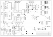
Here is my implementation for a ten amps system
JP
Attachments
We want a solution that will provide anti thump, can be triggered by some dc protection circuit and that can handle fault level currents worst case (amplifier output short circuited is worst for current, 2nd worst is output device short circuited to rai, l so about 20A). It must be fast and resettable i.e avoid having to replace fuses or similar since that's a distinct benefit. Further, it should never suffer any wear out mechanism, since it really has to be exceedingly reliable (so we do not ever have to worry about damaging speakers).
So far, only the mosfets can do that at reasonable cost. This is not 'ad hominem', it's a clear set of design objectives.
I will publish my protection board when my e-Amp is posted up sometime in the next few weeks - it handles all these things and is very simple.
So far, only the mosfets can do that at reasonable cost. This is not 'ad hominem', it's a clear set of design objectives.
I will publish my protection board when my e-Amp is posted up sometime in the next few weeks - it handles all these things and is very simple.
Last edited:
I have updated this document with some distortion analysis (LTSpice) and a few comments on fail safety.
Bottom line is you can expect <1ppm distortion reference the amplifer output signal at full power, and lower distotion at lower powers. I've also included some simulation data of the distortion of the signal appearing across the mosfets when they are turned ON.
http://hifisonix.com/wordpress/wp-content/uploads/2010/10/Solid-State-Loudspeaker-Relay-V1.0.pdf
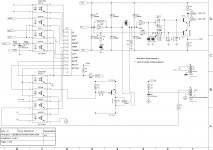
there are some examples of mosfet relay in japan...
attatched figure is from
‚QSK1529/2SJ200MonauralPowerAmplifier
another example
http://easyaudiokit.hobby-web.net/bekkan/MOSFETrelay/MOSFETRELAY.html
attatched figure is from
‚QSK1529/2SJ200MonauralPowerAmplifier
another example
http://easyaudiokit.hobby-web.net/bekkan/MOSFETrelay/MOSFETRELAY.html
Attachments
- Home
- Amplifiers
- Solid State
- Output Relays