Member
Joined 2009
Paid Member
Wavebourn - I love this soft clipping, I gotta figure how to 'proudly borrow' this into my Harry 77 amp design - where my goal is to make a guitar-style amp for hi-fi 😀
I don't have that diode model. I tried other types of Silicon and
Schottky in that position with negligible effect. Series resistance
seems to be dominant in that branch.
However, I do see what you mean about current limiting. Hardly
any difference in current seen between 2 ohm load and 1ohm....
Your amp tops out a little over 4 amps and refuses to self destruct.
Mine (s19.asc) tries to deliver 14 Amps into same 1ohm abuse.
Both tested with same 23V input...
Bigun said:Wavebourn - I love this soft clipping, I gotta figure how to 'proudly borrow' this into my Harry 77 amp design - where my goal is to make a guitar-style amp for hi-fi 😀
My pleasure! 😉
Member
Joined 2009
Paid Member
perfect !
I don't want to hijack this thread, so I started another one [http://www.diyaudio.com/forums/showthread.php?s=&threadid=146015&highlight=] . There's no hurry, I'm not going to be able to do much on it yet and I'm quite interested to follow this hybrid design.
I don't want to hijack this thread, so I started another one [http://www.diyaudio.com/forums/showthread.php?s=&threadid=146015&highlight=] . There's no hurry, I'm not going to be able to do much on it yet and I'm quite interested to follow this hybrid design.
kenpeter said:
However, I do see what you mean about current limiting. Hardly
any difference in current seen between 2 ohm load and 1ohm....
Your amp tops out a little over 4 amps and refuses to self destruct.
Exactly! 😉
I also made such amps long time ago (in 1980'th) for cars, owners liked to roll-over speakers shorting wires, and Japanese amps did not survive. Mine never destructed themselves. 🙂
Edit: I called it Aikido, but returning back from software to audio design I discovered that the name had been taken by Tubecad sticking forever to SRPP.
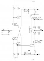
Wavebourn said:Try this one:
http://www.diyaudio.com/forums/attachment.php?s=&postid=1858788&stamp=1245364119
but replace D4 and D5 by 1N5711.
This output stage is bulletproof: it was designed for a guitar hybrid, but it sounds very nice with Hi-Fi amps.
Hello
How much current it need to drive it ?
Thank
Bye
Gaetan
gaetan8888 said:
Hello
How much current it need to drive it ?
About 0.5 milliamperes minimum, but I recommend about 100 times more idle current in your tube stage for better linearity. Don't forget about a coupling capacitor and couple of diodes to 25V rails to protect it's input transistors from overvoltages. You may use one triode strapped EL84 tube with 6 LEDs (2 parallel strings of 3 in series) in cathode, loaded on SVCS, like this one:
http://wavebourn.com/forum/download.php?id=125&f=7
You may remove D5 Zener in the SVCS (short it), decrease R7 to 24K, and power it from 300V instead of 500V. Tune R3 according to your taste.
Wavebourn said:About 0.5 milliamperes minimum, but I recommend about 100 times more idle current in your tube stage for better linearity.
My experience is to use more current, and lower driving impeadance is better.
Another thing: I have no good experience with CFP output, and tube drivers. I don't know what is the problem with it, but it never sounds good to me. (I found something in Self's measurements, which reported wrong input impedance response for CFP output)
Sajti
kenpeter said:
At DC maybe... Those gates won't charge/discharge themselves.
Without a change in gate charge (repeated every cycle) there is
no change in channel current. Regardless how much "capacitance"
a source follower topology might claim to hide, the energy wasted
over time goes up with frequency...
At audio frequencies. The IRF510/9510 have low Cdg (some 10pF), it even less than the commonly used driver transistors (MJE1503x). The Ugs change is very low, due the driver function
Sajti
sajti said:
My experience is to use more current, and lower driving impeadance is better.
Another thing: I have no good experience with CFP output, and tube drivers. I don't know what is the problem with it, but it never sounds good to me. (I found something in Self's measurements, which reported wrong input impedance response for CFP output)
We were speaking about my bulletproof Aikido output follower (not SRPP, it is a complementary 2-stage opamp with unity gain). Contrary to conventional output follower it's input resistance goes down when it shifts from class A to B.
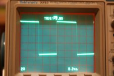
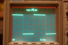
Hi Sajti,
would you have a screenshot in something like 10us/div, rather than 200us/div?
Thanks,
would you have a screenshot in something like 10us/div, rather than 200us/div?
Thanks,
Hi,
i need an opinion here....
i was playing with a output buffer concept for a hybrid power amplifier...thanks in advance....
best regards
daniel
I designed my own hybrid amplifier and simply bolted on an SRPP front end to a standard MOSFET class AB amp. Because the valve had a gain of 11 I had to reduce the gain of the MOSFET amp by that factor otherwise it was straightforward.
Last edited:
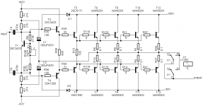
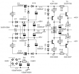
Hi, guys!
What do you think about this circuit? Is it good?
The only question is the bias, because there is no possibility to do any settings.
Sajti
The bias is adjusted by changing the values of resistors in the emitters of the first two transistors.
Do you think there is a danger of oscillations?
Do you think there is a danger of oscillations?
The bias is adjusted by changing the values of resistors in the emitters of the first two transistors.
Do you think there is a danger of oscillations?
That setting is possible, but it's not easy to set the bias by that way...
The oscillation is not a big issue without feedback. But some base stopper resistor can be good
Sajti
What type of chain I can add in scheme to easily tune the bias?
Where I can add base stopper resistors and what are their values?
Where I can add base stopper resistors and what are their values?
- Status
- Not open for further replies.
- Home
- Amplifiers
- Solid State
- output buffer for a hybrid amplifier