Hi,
i need an opinion here....
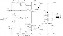
i was playing with a output buffer concept for a hybrid power amplifier... i would like You guys to tell me if this will be o.k.... an opinion is needed....
this in attach is only the output buffer of the amplifier - the input will be some tube stage with the gain of arround 10-12.... maybe an Aikido stage or just plain common cathode using one triode only - this has to be decided... i am thinking of using 5687 with a decent plate current and a ccs in the plate of the tube.... somehting like that... or Aikido stage with 6n6p tube or 5687 at the output.... this is still to be decided.... what i need you to tell me if this is o.k.... would it be good enough to try to build and to PROBABLY get a good result..... 😀
thanks in advance....
best regards
daniel
i need an opinion here....
i was playing with a output buffer concept for a hybrid power amplifier... i would like You guys to tell me if this will be o.k.... an opinion is needed....
this in attach is only the output buffer of the amplifier - the input will be some tube stage with the gain of arround 10-12.... maybe an Aikido stage or just plain common cathode using one triode only - this has to be decided... i am thinking of using 5687 with a decent plate current and a ccs in the plate of the tube.... somehting like that... or Aikido stage with 6n6p tube or 5687 at the output.... this is still to be decided.... what i need you to tell me if this is o.k.... would it be good enough to try to build and to PROBABLY get a good result..... 😀
thanks in advance....
best regards
daniel
Attachments
Hi Sparkle;
here is a good thread to start learning from:
http://www.diyaudio.com/forums/showthread.php?postid=1842408#post1842408
Don't learn from D. Self when building class A hybrid amps; he did not write his book about them. He wrote a book about some typical topology only.
here is a good thread to start learning from:
http://www.diyaudio.com/forums/showthread.php?postid=1842408#post1842408
Don't learn from D. Self when building class A hybrid amps; he did not write his book about them. He wrote a book about some typical topology only.
Wavebourn - thanks for the link - very nice informations there.... 🙂
===========
but... i wanted to hear an opinion about the design from the first post of this thread... and this is not Class A tube/mosfet design but push-pull class AB using transistors at output....
so, please - comments on that design and eventually informations on how to improve it - i am preety sure it will work - i want to improve it if possible - not to convert it to mosfet ...... thanks in advance and best regards
Member
Joined 2009
Paid Member
Hi Sparkle,
One question is, whether you will have even a little global-negative feedback to provide better damping factor as none is indicated in your first post ?
Edit: might you want to add a charge-suck out capacitor across the bases of the output devices. Helps with the cross over switch off of the devices ? A value of 100nF or so is common.
good point Bigun - i forgot about the suckout capacitor... thnx...
global feedback...
well - i'd like to go without it - but don't want to discard the idea of having it (maybe a little bit) too.... so, that is also an open question.....
global feedback...
well - i'd like to go without it - but don't want to discard the idea of having it (maybe a little bit) too.... so, that is also an open question.....
My experience is, that the high input impedance is the most important. So I would use triple darlington output, and use the 100uF caps as bootstrapping the resistor string. You can get 100-200kohms input impedance with this modification, and single stage E88CC can drive the amplifier.
Sajti
Sajti
This looks quite interesting, at least on paper.
BUT you must be able to make the bias setting adjustable, there is no hint of how much standing current you will get if you just build it up as drawn. I suggest the 22k in the BD139 circuit becomes a trimmer, a precision 10 turn trimmer if at all possible. And start it up with the trimmer set to zero ohms and open it slowly while monitoring the standing current.
Then it may be quite good.
But as someone else said, it will need a lot of drive current from the tube stage, but you don't go into that.
Regards, Allen (Vacuum State)
Sajti,
That looks really good and far easier on the tube stage! I'm tempted to try it.
And a correction to my previous suggestion regarding making the 22k a trimmer - that's unsafe, as if the trimmer goes open circuit the output stage will suddenly have huge current, far better to make the 8k2 the trimmer.
Then if it goes O/C the current just shuts down, not blows up.
Regards, Allen (Vacuum State)
sajti said:My experience is, that the high input impedance is the most important. So I would use triple darlington output, and use the 100uF caps as bootstrapping the resistor string. You can get 100-200kohms input impedance with this modification, and single stage E88CC can drive the amplifier.
Sajti
thank You for the interest - thanks for the adice - adding tripple darlington intead of the one output transistor - i will try that today in the evening... thanks.... regards
Allen Wright said:This looks quite interesting, at least on paper.
BUT you must be able to make the bias setting adjustable, there is no hint of how much standing current you will get if you just build it up as drawn. I suggest the 22k in the BD139 circuit becomes a trimmer, a precision 10 turn trimmer if at all possible. And start it up with the trimmer set to zero ohms and open it slowly while monitoring the standing current.
Then it may be quite good.
But as someone else said, it will need a lot of drive current from the tube stage, but you don't go into that.
Regards, Allen (Vacuum State)
Dear Allen, thanks for the interest - much appreciated.... yes - it looks interesting - i tried this concept with bootstrapped opamp as input... it was working fine - the bass was REALLY tight, had definiton... really good - but i felt opamp sound in general so i decided not to use it.... now i have a need to build a hybrid design and would like to use the same concept to get the best (well, o.k., not the best but really good) from tubes and from solid state.....😀
i forgot to draw the trimpot in Vbe multiplier - thanks for input - i willdo that later today... i wanted to use a trimpot on that position instead of 22k like you said....
yes, it will need a lot of current - i will deal with that - 5687 or 6n6p, 12B4 or something will do the job... the concept of the input tube stage is still open... i would like to deal with this output stage first, to build it and than to experiment with different input tube designs to see which one will do the job the best possible for the given output buffer.... that is my intention.... 😀
sajti said:
Sajti - my man!!!... thanks for this link... 😀
1. question - what are you using for the input to drive this output stage
2. question - how does it sound overall (on which equipment)....??
thanks.....
i like the idea of using those ccs's in emiter of the driver trasistors.... they really sound good ... i just have to make the rest of the circuit up to what they can do..... 😀
best regards to all... this thread is progressing nice - really thanks to all of You...
sparkle said:
1. question - what are you using for the input to drive this output stage
2. question - how does it sound overall (on which equipment)....??
thanks.....
i like the idea of using those ccs's in emiter of the driver trasistors.... they really sound good ... i just have to make the rest of the circuit up to what they can do..... 😀
Hi,
I use ECC99 to drive my amplifier. But I use it bridged (2 amplifiers drive with opposites phase signal), with 8 pairs of output devices. So 5687/ECC99, or E88CC can drive it easily. If You increase the rails to 40V, You can inrease the 6.2kohm resistors to 10kohm, the 5.6kohm to 9.1kohm, and the 1kohm trimmer to 2.2kohm. This will increase the input impedance as well.
I don't really tell the sound quality, because I used only as prototype, with small power supply, and lot of cables.
This is very simple circuit, so I don't use pcb, but point to point wire.
I can link pictures about the high power version.
Sajti
Here is the amplifier under test:
Sajti
An externally hosted image should be here but it was not working when we last tested it.
Sajti
sajti - looking really nice... 😀 thanks for sharing this with us...
....
i will update the sch (from the first post of this thread) later at evening today and than we can move forward.....
....
i will update the sch (from the first post of this thread) later at evening today and than we can move forward.....
Gents,
If you are looking for a really good sounding front end for these output stages, may I suggest the line stage of this FVP-5A preamp of mine:
http://www.vacuumstate.com/index.tpl?rubrik=8&lang=2&a=%252C%FC%EE%3AN%D1%CA%B2&b=733938.5618298185
With the superlinear cathode follower (SLCF) output you have the capability to drive almost anything, and it also sounds fabulous.
Regards, Allen (Vacuum State)
Allen, thanks for the suggestion.... i have seen Your line stage few years ago - it is also one option - a good one if i may say....
do You think that we SHOULD power it by using Your SuperRegulator or do You think it will sound superiour allready by using "normal" CLC filtering network.... (the reason i am asking this is because i do not have the information regarding that specific regulator and i would like to know how much i would be loosing regarding the quality.... thanks...
**************
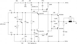
i have tried the darlington on my output transistors in output buffer from the post 1 in this thread... no good.... the square wave doesn't look square any more... it is more stabile when using one output power transistor - so i will stick to that option right now.....
here is the updated schematic with the components i forgot to draw.... 😀 thanks to You guys they are in the sch now 😀
thanks again...
do You think that we SHOULD power it by using Your SuperRegulator or do You think it will sound superiour allready by using "normal" CLC filtering network.... (the reason i am asking this is because i do not have the information regarding that specific regulator and i would like to know how much i would be loosing regarding the quality.... thanks...
**************
i have tried the darlington on my output transistors in output buffer from the post 1 in this thread... no good.... the square wave doesn't look square any more... it is more stabile when using one output power transistor - so i will stick to that option right now.....
here is the updated schematic with the components i forgot to draw.... 😀 thanks to You guys they are in the sch now 😀
thanks again...
Attachments
o.k. - this seems to be the result of this quest... nobody seems to want to add something.... then, i think i will go with this design....
thanks guys...
thanks guys...
As I measured my output stage there was no problem with the square wave response, up to 40kHz. The driver was ECC99 with Ra=22kohm, and Ik=9mA
Regards:Sajti
Regards:Sajti
Maybe LM3886 or LM3875 we can use as power buffer, but I'm not sure if it work propely in amplifikation = 1.
- Status
- Not open for further replies.
- Home
- Amplifiers
- Solid State
- output buffer for a hybrid amplifier