In all the output stages I simulated this was the most linear on 2 ohms and you also have the 1980's amp's specs :
Interesting, thanks!
Agreed. I drive my buffer with tube headphone amplifier, with ~50ohm output.Drive impedance and load impedance are important to know.
My buffer uses c5200/a1943 to drive the c5200/a1943, so it actually does not require any particular current to drive it.
Output I use for measurement is generic 6 ohm bookshelf speaker at moderate sound level I can tolerate. This is close to half the watt. I prefer real life conditions. That's wat matter to me. The buffer should not have problem to drive 6 ohm.
Is Altman still active? One of the most capable snake oil salesmen ever!Thanks for the info about the Altmann's web page, yes, that's what I have seen in the past.
Jan
You can call him..find his number at the end of the page :Is Altman still active? One of the most capable snake oil salesmen ever!
Jan
http://www.mother-of-tone.com/byob.htm
He seem to be very much alive and thriving...
http://www.altmann.haan.de/
Hi adasonAgreed. I drive my buffer with tube headphone amplifier, with ~50ohm output.
My buffer uses c5200/a1943 to drive the c5200/a1943, so it actually does not require any particular current to drive it.
Output I use for measurement is generic 6 ohm bookshelf speaker at moderate sound level I can tolerate. This is close to half the watt. I prefer real life conditions. That's wat matter to me. The buffer should not have problem to drive 6 ohm.
Just saw your "viral" thread, great stuff! How does the bipolar buffer compare to the LU1014 circuits?
Best,
cv
F3 is the cleanest, F1J with LU is most fun.Hi adason
Just saw your "viral" thread, great stuff! How does the bipolar buffer compare to the LU1014 circuits?
Best,
cv
My buffer with tube pre is more 3D.

Remember, the sound of the buffer is miniscule to the sound of your pre. Pre dictates the results, but the buffer confirms it.
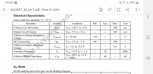
What is the maximum Iq for one pair of 2SC5200/2SA1943 BJTs? Does the circuit not need thermal sensing? Thanks.
I measured the relationship between the bias and distortion and went from very low current few milliamps to all the way to 0.5A per output. That graph is ploted on the thread linked in first post.
Otherwise you can go as high as 15A if you manage cooling. Its in the Table i posted above.
The distortion drops significantly with increasing current, but its not linear and there is diminishing return. I run ~0.4A now.
I found no need for temperature sensing. Does F4 buffer use thermal sensing?
Otherwise you can go as high as 15A if you manage cooling. Its in the Table i posted above.
The distortion drops significantly with increasing current, but its not linear and there is diminishing return. I run ~0.4A now.
I found no need for temperature sensing. Does F4 buffer use thermal sensing?
Last edited:
Thank you for your reply. I hope both of us are referring to schematic in post #16 as you mention 0.4A per BJT. In F4 and all other First Watt Amplifiers there is no thermal sensing employed as Vertical FETs' thermal coefficient transitions from positive at higher quiscent currents. What is the thermal rating of the heatsinks at 0.4A bias?
Do you think we could change the driver transistors from 5200/1943 to lower Cob types?
I plan to use MJW types for the Outputs. Thanks.
Do you think we could change the driver transistors from 5200/1943 to lower Cob types?
I plan to use MJW types for the Outputs. Thanks.
Whats wrong with c5200/a1943?
Do you need response above 10MHz?
Feel free to use any outputs you have.
F4 has mosfets, not vfets.
Do you need response above 10MHz?
Feel free to use any outputs you have.
F4 has mosfets, not vfets.
In the table post #21, c5200/a1943 are outputs with lowest Cob. All other outputs i have have only bigger Cob.Thank you for your reply. I hope both of us are referring to schematic in post #16 as you mention 0.4A per BJT. In F4 and all other First Watt Amplifiers there is no thermal sensing employed as Vertical FETs' thermal coefficient transitions from positive at higher quiscent currents. What is the thermal rating of the heatsinks at 0.4A bias?
Do you think we could change the driver transistors from 5200/1943 to lower Cob types?
I plan to use MJW types for the Outputs. Thanks.
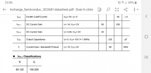
Just curious to try. Lower Cob driver transistors might mean higher resolution music. That's my experience.

Except you want to equal top 1980's amplifier performance that today aren't anywhere to be found in any price range...
My buffer has 0.011% thd at normal listening level. Why would i want to build that with ~0.8% thd and more at higher fr.
Except you want to equal top 1980's amplifier performance that today aren't anywhere to be found in any price range...
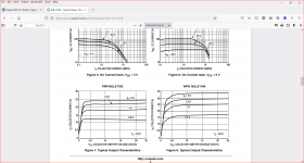
These transistors have been used in recently published magazine published designs that give THD of <0.008%, 20Hz-20kHz at 32W into 8R. These results are test proven using Audio Precision equipment not simulations. The design follows the Blameless model which uses nfb to attain that level and operate at a low level of Class AB. If you look at the graphs below you will see these have linear operating characteristics at high current levels. These plots would look even flatter with lower base currents and operating in Class A.My buffer has 0.011% thd at normal listening level. Why would i want to build that with ~0.8% thd and more at higher fr.
This design was tested with a variety of output devices and drivers included the closely related NJW21193 and NJW21194 which were standard as well as 2SC5200 and 2SA1943 which were verified as meeting the same standard as the NJW parts. The humble TIP 35B and TIP36B were performance verified for surprisingly good performance.
The project title is Hummingbird Amplifier which has a compact pcb and uses through the hole components- this published by Silicon Chip magazine in December 2021 and January 2022 issues. Pages of these can be downloaded from their website for a modest cost.
I buy this magazine as it covers a lot of material in the electronics domain and I can get this monthly from bookshops. There is a very interesting series of articles discussing the history of transistors with various technical insights - food for the brain. I am not planning to build this amplifier project myself.
Attachments
You are talking about distortion of an amplifier with negative feedback. That's exactly what i am trying to avoid.
- Home
- Amplifiers
- Solid State
- Output BJTs for buffer