
Hi Vunce,
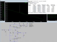
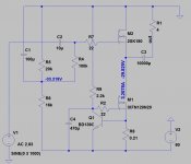
this one is from the LTSpice with actual values as on the prototype. R5 & R6 are 500 Ω trimmers. I didn’t fire up KiCad yet. 🙂
Will check before if circuit behaves better with JFET CCS instead of DN2540.

this one is from the LTSpice with actual values as on the prototype. R5 & R6 are 500 Ω trimmers. I didn’t fire up KiCad yet. 🙂
Will check before if circuit behaves better with JFET CCS instead of DN2540.

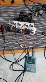
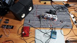
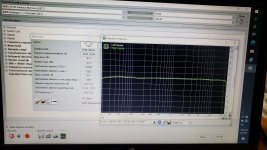
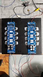
Back from vacation, finished the buffer with 3281/1302. With +/-22 volt power supply, took the bias to 100mV on 0.22 resistors, which translates to 0.454A. Took some measurements at 2.69Vpkpk, or 914mV rms into 6 ohm real speaker.
Attachments
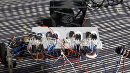
Offcourse had to use forced air for now based on the size of heatsink. Btw, adjustment for these outputs could use bigger trimmer or 10k increased. Each type of outputs is slightly different.
Interesting thing, I noticed slight hump, really slight, just a dB, on low fr response, not sure why. Otherwise the buffer sounds very good, surprisingly good, considering just test bookshelfs for now.
Interesting thing, I noticed slight hump, really slight, just a dB, on low fr response, not sure why. Otherwise the buffer sounds very good, surprisingly good, considering just test bookshelfs for now.
Attachments
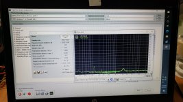
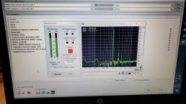
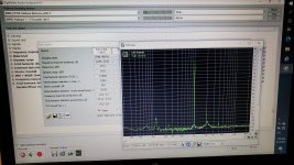
I agree that distortion is likely lower. LTSpice simulation calculates for 2.7 Vpp to 6Ω load, 0.00325 % distortion at 0.46 A Iq. As LTSpice distortion calculations with Bob Cordell BJT models are pretty close to measured ones, distortion is probably less than 0.005%.It measures impressively low thd 0.0085%, which is likely lower, had to use nuforce dac, as rta software refused to with with just focusrite alone.
My listening session continues and I’m more and more convinced that there is some very high hidden quality in this simple wide power bandwidth, high slew rate, low distortion and no GNFB circuit. I’m occasionally rewarded with undiscovered soundstage gems.
Attachments
Is there a specific reason for the douglas Self type 1 output stage? Would type 2 have some benefits? ( removing connection from output to midpoint of driver emitter resistors)
There seems to be no advantage with type 2, as output stage works in class A for all intended output levels.
I find simple diamond buffer with CFP to work amazingly better. At 1 A bias and +- 15V supply, dissipation is low enough, output power is 10 W/ 8 Ω, distortion very low up to max. output. Slew rate, noise levels, power bandwidth and output impedance are all really good. Distortion profile is monotonic at all output levels with dominant, negative phase H2.
No wonder that long listening period makes me contemplating if I need anything better.
;-)
My experience:
TO-3P-types sound not good: shallow, mild but slow, not contoured, cloudy. The smaller the case of transistors the better the sound (exacter "flow", "current")
Paralleling brings impurities, abrasion of contour.
PCB brings material character of plastic, paper, and catches unnecessary resonances.
Most time a little clean sounding amp or follower will do the job better. First I would try a se. If it does not the job, then I would try a simplest pp-follower: 2 diodes, 2 trimer, 2 transes, 2 power-resistors only. Transes: TO-220 or, bit better, fullpak.
I have seen your two threads you started, and thats plenty for me not to take anything you say seriously.
You cannot proove you can hear differences of these at all in a double blind test.;-)
My experience:
TO-3P-types sound not good: shallow, mild but slow, not contoured, cloudy. The smaller the case of transistors the better the sound (exacter "flow", "current")
Paralleling brings impurities, abrasion of contour.
PCB brings material character of plastic, paper, and catches unnecessary resonances.
Most time a little clean sounding amp or follower will do the job better. First I would try a se. If it does not the job, then I would try a simplest pp-follower: 2 diodes, 2 trimer, 2 transes, 2 power-resistors only. Transes: TO-220 or, bit better, fullpak.
Hi cumbb,
You know, it is the exact same die used in both case types. The exact same part and the case will not affect the signal anywhere near audio frequencies.
You are basically hearing things (expectation bias) because those differences simply do not exist.
-Chris
You know, it is the exact same die used in both case types. The exact same part and the case will not affect the signal anywhere near audio frequencies.
You are basically hearing things (expectation bias) because those differences simply do not exist.
-Chris
The different case is the cause;-) Minimal other materials. And minimal other contacts to e.g. heat sinks. And so on.Hi cumbb,
You know, it is the exact same die used in both case types. The exact same part and the case will not affect the signal anywhere near audio frequencies.
You are basically hearing things (expectation bias) because those differences simply do not exist.
-Chris
"Flow", not simply "current". We do talk about a complex process. And use a high complex measurement method: hearing!
I suggest: Grind, cut your transistors to test;-)
Hi cumbb,
Ahh, no. You are off into the weeds on this.
These days we routinely measure things well below the ability of the human body to perceive. Do you understand what that means? It means you are talking nonsense.
I understand how transistors (electronic devices in general) work on an atomic level, and also from an electric field level. What you are saying simply doesn't happen, I'm sorry. So, where ever or whatever you are reading to get this information - stop. It's wrong, simple as that. Tin foil hat time folks!
;-)Hi cumbb,
Ahh, no. You are off into the weeds on this.
These days we routinely measure things well below the ability of the human body to perceive. Do you understand what that means? It means you are talking nonsense.
I understand how transistors (electronic devices in general) work on an atomic level, and also from an electric field level. What you are saying simply doesn't happen, I'm sorry. So, where ever or whatever you are reading to get this information - stop. It's wrong, simple as that. Tin foil hat time folks!
Okay: The simplest test: use (double) mono-psus. And then connect these. With a switch at the listening position, if you like. And switch back and forth as long as you need it. And will admit: Same components, same layout, different sound. And then, after the "observation", explain.
Electrophysics is much more complex than is taught at universities, for example.
Hearing as well;-)
Hearing as opposed to what actually hits the eardrum involves interpretation by the brain. I have a good understanding of what people can think they hear, and basically the brain exerts a far greater influence on what you think you hear than what is actually "heard". This is your problem.
Expectation bias. This is your explanation pure and simple. Couple that with confirmation bias and we have a person who ignores all other evidence that opposes what they have become invested in.
Universities only ever teach the basics coupled with how to learn. It is further education and reading plus direct controlled experience that brings a full understanding.
Now, the human body makes a very poor instrument. We are designed very well how to survive in dynamic situations. We do not have built in references, we can only compare. But our mind overrides and processes all inputs. We recognise danger or safe patterns and act accordingly. that is what we are optimised to do. In addition, we have a limited s/n ratio as our bodies are noisy. Then there is the environment which will have a noise floor greatly above what you say you are hearing. Finally, there is your experimental setup. It can be extremely difficult to design an experiment that eliminates or at least controls factors outside of the thing we are investigating.
You will disagree with what I am saying to you of course. I would suggest you quietly assess what has been said, then research the facts before saying anything else. This is not going well for you.
-Chris
TO-3P-types sound not good: shallow, mild but slow, not contoured, cloudy. The smaller the case of transistors the better the sound (exacter "flow", "current")
Paralleling brings impurities, abrasion of contour.
PCB brings material character of plastic, paper, and catches unnecessary resonances.
I sort of share some of the concerns above, but also find it difficult to make hard generalisations.
As it happens, the two most recent amps i have built and enjoyed are both followers, but more different than alike. Both are built as mono blocks.
The first one is based on a THF-51 SIT running at around 3A/30v with a CCS underneath, so a 60v PS. Two coupling caps, a polystyrene Multicap at input and a 10mF Cerafine at output. No pcb. Separate transformer/rectifier/regulator for setting the biasing voltage.
The second is a diamond buffer with 4 pairs 3281/1302 based on a circuit by diyaudio member SandyTodorov1. No coupling caps. 2.2A @ +-34v
Both have very low distortion at low power, and the SIT gradually increases in distortion towards its terminal 15W 4ohms while the PP amp preserves sub 0.01% distortion at higher powers. Tried running the diamond buffer at various currents between 1.6 and 4A before settling to 2.2A. The highest current did not sound particularly pleasing to me.
So, how do both amps compare at low listening levels but into a pretty demanding load which occasionally dips below 3ohms?
The SIT certainly has a charm and highlights voices and cellos. Does not do particularly well at either of the frequency extremes, has a narrower soundstage and significantly less detail. Still, very enjoyable.
The PP amp has a slightly cooler tonal balance, still does justice to voices and can suit a wider selection of musical genres. It also sounds faster, taller and wider but perhaps shallower.
There are some build differences between the amps. The SIT uses 4320 based rectifiers while the PP amp has the cheapest chinese bridges money can buy.
Some of my prejudices like SE operation and coupling caps seem to be justified in this comparison, while others are not. Neither the plastic cases, nor the multiple parallel devices, nor the pcb with a mask seemed to subtract enough from the PP amp performance. Ditto for the emitter degeneration resistors.
I intend to still try 4320 and Ge rectification in both amps and also to build a version of the PP amp with Sanken outputs instead of ON semi.
Below are the general circuits used.
Attachments

- Home
- Amplifiers
- Solid State
- Output BJTs for buffer