I have an OTL amp - it is designed to use four 6C33C's per channel (just over 50W), I only use two per channel, giving me about 25+W connected to a pair of Sonus Faber Grand Piano home (min. 6ohms).
in my living room ( 5m X 4m) at 2/3 power, the room is shaking!
Sound is excellent, all the way from subsonic to ultrasonic.
Why do some people need 100W or more in average sized rooms, is beyond me.
There is a school of thought that claims:
When clarity and resolution is missing in a HiFi system, it is human-nature to pump up the volume, in an attempt to hear what one can not hear.
I am a firm believer in that, if the source has plenty of resolution, playing Hendrix or Boston at moderate levels becomes very enjoyable, no need for 100's of watts - unless you are in a huge room, with huge speakers!
Last edited:
Hi,
No one probably needs such highish power but when it comes to commercial OTLs you easily approach such power output when designing for low impedance speakers because you want low Zout before applying NFB.
Which implies lots of valves in parallel to get there.
Cheers, 😉
Why do some people need 100W or more in average sized rooms, is beyond me.
For example ,
Friend of my use two OTL ~100W monoblock to power two Apogee Duetta II (4-ohm) magnetostats ,
those low efficiency magnetostats need that power to start to sing ,
each amp use 6 x 6c33c-b power tube and those amps are directly based on Atmasphere OTL design , with only four inserted 6c33c power tubes per amp hi can not get that right dynamic sound impact , but with the six is the right thing .
Edit , those OTL`s are 100% GNFB free .
Last edited:
If one were to use 6336s in the Atma-Sphere M-60 design, 4 power tubes would achieve 60 watts into 8 ohms. You need the same number of 6C33s to make the same power. This version of the M-60 is a little closer to what we make today:
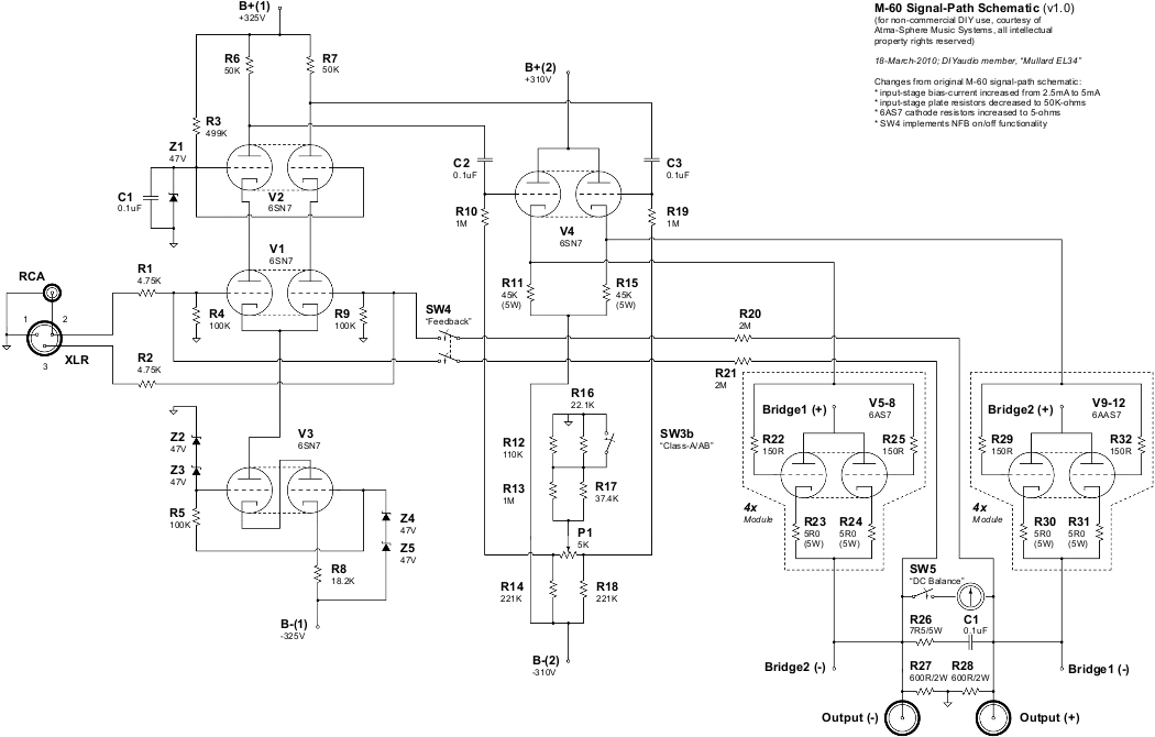
We built a 6336-based amp as a prototype many years ago.
Alternatively you could use 7241s; a pair of those would get 50 watts into 8 ohms, but they are really hard to find and pricey!
With regards to the 6336: unlike the 6AS7G and 6080 the tube is prone to hard shorts during arc-over conditions. For this reason it is a really good idea to put a fuse in series with each tube if not each section. I would also use a 5 Ohm 7W resistor in series with the cathode of each section.
Since the mu is a little higher the bias voltage will be slightly less negative than shown in our schematic. Its not a huge concern and easy to adjust. If you don't have a direct-coupled driver this tube is going to give you fits; from that perspective the Futterman circuits are going to be marginal- either your bias is going to drift, there will be no bass or both.
The grid stop resistor should be able to handle some power in case the tube shorts. We use 150 ohm 1 watt devices that hold up quite well with 6AS7Gs, but a 6336 is going to be more abusive if it shorts. If you don't expect to run grid current (and with the Futterman, you won't) then the grid stops can be a higher resistance and may be less prone to failure.
The reason you want to consider being able to run grid current is the fact that this triode, not unlike the 6AS7G, is going to have some grid current occurring before the grid is even at the cathode voltage. So you will have linearity problems if you don't have a gutsy driver circuit.
One other consideration: the 6336 should only be used with ceramic sockets of good quality (no Chinese stuff) with tin-plated pins else you will be replacing the sockets on a service schedule; the sockets run quite hot!
There is really no need for a 64 ohm speaker!! 16 ohms should work beautifully with nearly any OTL of 50-60 watts!
If you cascade two stages of gain you have to deal with either an extra coupling capacitor or some sort of AC balance means (which often adds more distortion than it removes). OTLs being as transparent as they are, its easier to hear the effects of coupling capacitors with them. Plus I want to keep the LF phase shift minimized and a second frequency pole complicates that.
Turns out if you run enough current (as opposed to how Valley/Wallman describes it) on a cascode you get more gain, not less, better bandwidth and lower distortion all at the same time- something pretty rare in audio circuits (usually its 2 of those aspects at the sacrifice of the 3rd).
With the cascode we don't have to hand-pick the tubes involved to make it work. If it was a direct-coupled cascade hand-picking the tubes would be mandatory. So there is a bit of plug and play going on as well; easier to deal with in the field.
It looks like the cascode has a gain of 60 per side, so an overall gain of 30 if driven single ended. Is that correct? It also looks like roughly 2mA per side.
That M60 is a circlotron, needs 4 power supplys and several separate heater voltages ( to avoid exesive Vfk ).Also the cascodes are rather useless, they only drive a pair of high input cathode followers.I love circlotrons but not this one.
Mona
Mona
It looks like the cascode has a gain of 60 per side, so an overall gain of 30 if driven single ended. Is that correct? It also looks like roughly 2mA per side.
That sounds about right. Overall gain is about 25db when taken at the output.
Last edited:
That M60 is a circlotron, needs 4 power supplys and several separate heater voltages ( to avoid exesive Vfk ).Also the cascodes are rather useless, they only drive a pair of high input cathode followers.I love circlotrons but not this one.
Mona
One heater supply is used without any reliability issues.
The output B+ is supplied by a single transformer with dual secondaries. The driver B+ and B- is provided by a separate power transformer with a single bridge rectifier.
Obviously without apparently much experience with the circuit, all I can say is you really need to spend more time analyzing it before making such comments. The cascode circuit works much better than cascade circuits- we did of course try them, and we have heard others that employed such and hear the same problems in them that we heard in our own before going to the cascode. Either way you still need the cathode follower driver.
Do you get any HF peaking because of the unusually high value of the feedback resistor?
You've probably noticed that there is no compensation 🙂
The bandwidth of the output section is pretty high- we have built prototypes that had bandwidth out to 30MKz and actually worked effectively as a boot for a CB radio, without harmonic issues😀. Production units of course have the bandwidth limitation built in, limited to 100KHz or 300KHz depending on which version and model. With bandwidth like that there is no peaking. Instead we just see a very gentle rolloff, nice for not inducing phase shift.
However its not really a big influence as the feedback is rather slight...
If my questions are annoying, don't hesitate to tell me, I'm just trying to understand the design logic better since I intend to try to build my own version of a circlotron OTL at some point (read: when I have the right speakers).
So, back to the cascode. You get a gain of roughly 30 (single ended input) from it. Why is that preferable to using a simple diff amp, no cascode or cascade, but with a higher gain tube than the 6SN7?
So, back to the cascode. You get a gain of roughly 30 (single ended input) from it. Why is that preferable to using a simple diff amp, no cascode or cascade, but with a higher gain tube than the 6SN7?
So--Looking at it--That Cascode stage is bascically a Cascoded Long-Tailed Pair phase-inverter and there's a CCS in the tail....
Hmm--Very clever.....
Hmm--Very clever.....
Last edited:
If my questions are annoying, don't hesitate to tell me, I'm just trying to understand the design logic better since I intend to try to build my own version of a circlotron OTL at some point (read: when I have the right speakers).
No worries!
So, back to the cascode. You get a gain of roughly 30 (single ended input) from it. Why is that preferable to using a simple diff amp, no cascode or cascade, but with a higher gain tube than the 6SN7?
Bandwidth. We used to use 12AT7s but the 6SN7 sounds better. Thought about using the 6SL7 for about 10 seconds.... but you can't get the bandwidth from one even though it would be pretty good as a differential amp, not without sacrificing the gain. You do need some gain- some people are going to use a speaker of only 89 db...
So--Looking at it--That Cascode stage is bascically a Cascoded Long-Tailed Pair phase-inverter and there's a CCS in the tail....
If you really want a differential circuit to work, you gotta have a 2-stage CCS!! One stage won't do it (although its better than nothing). I am amazed at how often performance is left on the table when one stage is used.
With a 2-stage CCS the input gain stage is nearly impervious performance-wise to some fairly large variations in power supply voltage- so the AC line can vary from about 100V to 130V without affecting linearity.
Thought about using the 6SL7 for about 10 seconds.... but you can't get the bandwidth from one even though it would be pretty good as a differential amp, not without sacrificing the gain.
That seems curious, since the next stage is a cathode follower. You're only charging 3-4pF. If one uses a 120k plate resistor, the f3 is over 300kHz. That's not CB territory, but ridiculously more than you need for audio. What am I missing?
Hi,
Not much other than the quest for extreme bandwidth and a smooth roll off really.
Audio myths, Stewart, audio myths........
Go ahead with that OTL, it's an ear opener really.
Oh, and what kind of speakers do you think you need to build?
Cheers, 😉
What am I missing?
Not much other than the quest for extreme bandwidth and a smooth roll off really.
Audio myths, Stewart, audio myths........
Go ahead with that OTL, it's an ear opener really.
Oh, and what kind of speakers do you think you need to build?
Cheers, 😉
Last edited:
Well I looked again, still don't like it 😀One heater supply is used without any reliability issues.
The output B+ is supplied by a single transformer with dual secondaries. The driver B+ and B- is provided by a separate power transformer with a single bridge rectifier.
Obviously without apparently much experience with the circuit, all I can say is you really need to spend more time analyzing it before making such comments. The cascode circuit works much better than cascade circuits- we did of course try them, and we have heard others that employed such and hear the same problems in them that we heard in our own before going to the cascode. Either way you still need the cathode follower driver.
V3 has a cathode at -225V.You can get away with that by polarising down the heater circuit (not to much considering the other tubes).The output has better it's own heater supply, the cathodes swing with the output, we don't want tht coupled back to the pre-cathodes.
Based on the your negative bias voltage I put in some voltages in red and an alternative in blue.Gives less drive voltage needed and less supply power.
How long the 6AS7 will last in this amp ? Ik max.=125mA (datasheet) but peaks of 500mA 😱
A DC protection for the speakers is advisable I think.
Mona
Attachments
- Status
- Not open for further replies.
- Home
- Amplifiers
- Tubes / Valves
- OTL with custom 64ohm speakers... Idea in the making