Hi,
Why not use a Taki OTL?
Uses a EF86 and a pair of ECC85s IIRC. Works great once you spotted the error on the circuit diagram.
Taki 6336A OTL
The PSU may need some beefing up though. Higher value caps and some judicious bypassing with good polyprops.
These electrolytics are invariably in the signal path in all OTLs I know of.
I fully agree that separate windings (better still separate xformers) is what you'd want for the positive and negative rails for the output B+.
Oh, I almost forgot. The quality and power rating of the powerxformers for the output stage are of utter importance. They should be massively overspecced and really well built.
Ideally huge chokes as well but nobody does that because of the cost.
But common heaters for the entire thing? Really??
Cathodes are input nodes and there's always some capacitive coupling going on.
Cheers, 😉
Last edited:
Hi fdegrove !
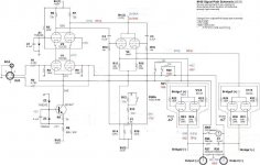
You are right , that Taki schematic have one capital mistake and is pretty incomplete ,
- negative bias source for lower pair of output 6336A was drawn with opposite polarity ( very dangerous situation )
-Filter capacitors on the same negative bias source is drawn with to high values ( 2000uF+1000uF ) , 200uF+100uF is correct value
-Bootstrap capacitor value is 40uF
-On the lower ECC85 anode resistors junction ( 2K2+10K) need another 40uF to be connected to -160VDC line .
-On the +490VDC line is missing first filter capacitor , which can be with 100uF value , or even slightly bigger value .
- Electrolytic capacitor which is in connected in parallel with 100K bias pot is 47uF value .
- Each 6336A triode section need 1R resistor to be connected in series with Each separate cathode ,but not as is drawn connected in anode circuit .
- 6.3V~ filament supply for two upper 6336A tubes need to be separate from lower 6336A tubes , where upper fil.supply need to be referenced on the common ground point , but lower fil.supply need to be referenced on the -160VDC line .
- 6,3V~ filament supply for EF86 & two ECC85 need to be referenced to common ground point to , via two 100R resistors , but not to stay floating as is in the wrong drawn schematic .
Here is corrected schematic , but I don`t exclude any other further correction or modification of this Taki design .
Attachments
Last edited:
10-4 banat thank you... with this being out of the audio signal path, would it be a huge loss to use solid state for this duty?
I'm about 11ft from each speaker when at the focal point, room is 14x19, speakers being on the corners of the long wall.
You can use solid state; I recommend a two-stage CCS of similar topology to what you see in the schematic. You will find though that the voltage drops are a problem for dissipation in the devices- you might want to drop a bit of the voltage across a bypassed resistor first.
I'm getting my tube numbers confused... I have tons of 12AU7's, a much closer sub to the 6SN7.
12AU7s are similar to 6SN7s but do not sound as good. Nor do they have the same filament/cathode arc-over rating. The 6SN7 is simply a better tube.
you might want to drop a bit of the voltage across a bypassed resistor first.
Bypassed? Why?
You can use solid state; I recommend a two-stage CCS of similar topology to what you see in the schematic. You will find though that the voltage drops are a problem for dissipation in the devices- you might want to drop a bit of the voltage across a bypassed resistor first.
Just for fun, since I just found a SPICE model for the M60 that I constructed a while ago, I took a look at the functioning of the V3 constant-current device. It works pretty impressively! With 1.5V input to the amplifier, which would be about 25W output into 8 ohms in my simulation of the M60, the current through the CCS varies between 2.70137mA at the trough and 2.70149mA at the peak of the sinewave. That's constant to better than one part in 20,000!
Chris
If I calculate correctly, there's a total swing of 1.5V and a current change of 0.00012mA. So that would suggest that the CCS impedance was 12k5. Or did I slip a decimal place?
If I calculate correctly, there's a total swing of 1.5V and a current change of 0.00012mA. So that would suggest that the CCS impedance was 12k5. Or did I slip a decimal place?
A few, maybe 🙂 . In fact in the sim I'm seeing about 1.8V total swing, and the current swings by 0.12 microamps. So that would be about 15 megohms. I suppose that's pretty good, right?
Chris
But this in series with the output of a CCS, right? Maybe I'm misunderstanding where the resistor goes in the circuit?
In series with the input. The idea is if you are going to use semiconductors, instead of dropping 300V across the CCS, drop maybe 200V instead- to reduce dissipation issues in the semiconductors.
OK, that clears my puzzlement. When I use resistors like that, I place them between the CCS and the circuit so that they don't need bypassing.
.. but then Vhk difference will be even greater if we go SY's way.. too great to safely use single heater supply, i'd say.
If i have to use one single heater supply and opted for Solid State CCS, i would power the heaters with -12VDC and use it for the SS CCS as well. LM317 CCS needs only 4V to work so 12V is plenty and dissipation will be minimum. Perhaps change the cathode follower V4 to 12SN7 and string the 6SN7 cascode LTP heaters.
If i have to use one single heater supply and opted for Solid State CCS, i would power the heaters with -12VDC and use it for the SS CCS as well. LM317 CCS needs only 4V to work so 12V is plenty and dissipation will be minimum. Perhaps change the cathode follower V4 to 12SN7 and string the 6SN7 cascode LTP heaters.
So, back to the cascode. You get a gain of roughly 30 (single ended input) from it. Why is that preferable to using a simple diff amp, no cascode or cascade, but with a higher gain tube than the 6SN7?
A cascode LTP up front has its advantages. For a project (Le Renard), I first considered cascoded 6SN7s, but these gave AV= 40 (phase-to-ground) that wasn't enough for good sensitivity with gNFB. I went with the 6BQ7 -- a higher gain type originally intended for VHF cascodes, that have a u-factor that falls nicely between the 6SN7 and 6SL7 that did give enough gain. This eliminates a gain stage for improved phase performance under gNFB.
Though a single 6SL7 will give nearly the same gain as a cascoded 6SN7 (~50 in either case) the much reduced input capacitance, due to greatly reduced Miller Effect, makes the cascode play nicer with a high resistance volume pot, so no need for input buffering. The other is greatly reduced distortion (why cascodes are used so frequently in SS designs). Audio use is never mentioned in the data sheet for the 6BQ7, and it does have some squirrelly plate characteristics (undocumented variable-u characteristic?) that make good audio loadlines difficult to find. However, the cascoded LTP has excellent sonic performance, very clean, very little distortion. The main disadvantage to cascodes is the greatly increased effective rp that makes for poor PSRR, nor does it like Hi-C loads. In this regard, it's a lot like a small signal pentode. Grid drivers help here in that a cathode follower is a much friendlier load.
Use active tail loading (I prefer cascoded BJTs for this) and a cascode LTP is an excellent performer.
.. but then Vhk difference will be even greater if we go SY's way.. too great to safely use single heater supply, i'd say.
If i have to use one single heater supply and opted for Solid State CCS, i would power the heaters with -12VDC and use it for the SS CCS as well. LM317 CCS needs only 4V to work so 12V is plenty and dissipation will be minimum. Perhaps change the cathode follower V4 to 12SN7 and string the 6SN7 cascode LTP heaters.
We've already proven that there is no safety issue with the 6SN7s going with Sy's suggestion. Our smaller amplifier, the S-30, until quite recently used to use a cathode resistor to B- (-300V) with no CCS at all. We had been doing that since 1997 when the S-30 was introduced. We had zero reliability issues with the bottom tube of the cascode. So we know that is simply a non-issue.
With only a resistor from the cathode of the bottom tube to -300V it isn't the Vhk but more the Vgk I 'm worried about.
In the mean time, done some puzzeling on the after all interesting M60 😉
With russian 6C33's and other changes there also is much more gain, allowing more GNFB.Will I ruine the amp this way ? 😀
Mona
In the mean time, done some puzzeling on the after all interesting M60 😉
With russian 6C33's and other changes there also is much more gain, allowing more GNFB.Will I ruine the amp this way ? 😀
Mona
Attachments
- Status
- Not open for further replies.
- Home
- Amplifiers
- Tubes / Valves
- OTL with custom 64ohm speakers... Idea in the making