The DC voltage at the cathode increased with signal input level? That's odd for a class A stage.
If you add a plate load resistor to restrict current flow, and also have K resistor, doesn't that just create an unbalanced cathodyne without a plate signal output? If you have a plate load resistor there will be a signal there that needs to be bypassed like common cathode bypassing is done? Yes?
Okay, here's the asc file of the current version and the models. I do want to thank you all for spending time thinking about my silly amplifier.
Connecting the current source to the output and using the ac directive, you can see the output impedance looks like this:

So about 87 ohms for almost all of the audible range.
I'll take a look at the load line sheet again and see what I can do, though as a cathode follower the gm is less important and it only seemed to raise the Zout slightly given the above graph.
Again I appreciate all your input. I admit that a lot of these choices are based on what the simulator says rather than theory or doing the math myself, and that may have some limitations. More than happy to try some different solutions!
Connecting the current source to the output and using the ac directive, you can see the output impedance looks like this:
So about 87 ohms for almost all of the audible range.
That R1 resistor is reducing the gm of your KT66, increasing Zout and worsening performance. It may be better to bias the KT66 cooler to prevent it from overheating at high output levels. It will still be in class A because the circuit is single-ended.
I'll take a look at the load line sheet again and see what I can do, though as a cathode follower the gm is less important and it only seemed to raise the Zout slightly given the above graph.
What I've been doing is putting 2.8V on the source to mimic 2Vrms standard output from a DAC and setting the potentiometer to 25% (0.75) which produces about 14mw into 300ohms with 0.134% THD. Turning the wiper up to 75% (0.25) gives me 120mw into 300 ohms and 1.44% THD, though I have trouble imagining turning the volume up that high. If I remove R12 and turn the wiper all the way up, I get an anode current of 85mA and 300V (the full B+) which is about 25.5W which is just over the recommended max of the KT66 (I remember it being higher last time I did this but I may have fiddled with things since then). What worries me more is if I up the source voltage to 5.6 to mimic 4Vrms (which is the actual output voltage of my DAC), the anode current goes up to 113mA which is 33.9W, well over the absolute maximum of the KT66. However, when I add back the resistor, the current clips at 84mA, and it thus becomes impossible to melt the tube no matter how high the source voltage. (I think the thing should be designed so that you can't melt your tube if everything's functioning properly, I don't know about you.) That all said, you may be right that I can change the bias of the tube to achieve the same effect, I can play with it.3. You wrote "Which in the sim has 0.13% THD." At what output level and into what load? Was that 1Vrms into 300 ohms? Or 1mW into 300 ohms?
Man I really wish I had schematics for those amps, it would make my job so much easier here.I can't tell anything about those commercial headphone amp designs you mentioned because there are no schematics, etc. in the documentation.
So if you go back to the beginning of the thread you can find a whole conversation about biasing the 12au7; the first version I tried had too much gain, the second version had almost no distortion but would melt the tubes like ice cream. Basically these settings were to lower the gain to the point where it wouldn't cook the KT66. At least in the model, the THD is still very low.The 12AU7 is running very current starved (Ip only 1.4mA), which means its rp must be somewhere up around 15k ohms. You put a plate load R8 of only 20k ohms, which is not even twice the 12AU7's rp at that operating point. That does give you low gain but it also brings high THD and possible problems driving the grid of the KT66 -- especially if it's wired in triode (higher input capacitance due to Miller effect). What led you to choose those operating points and parts values for the 12AU7?
So in the simulation, with the bypass cap the THD is 0.134%, without the bypass cap it's 0.243%. Try it yourself! I don't know why. It's possible a different operating point would change the equation, I could fool around with it more, but I figured why mess with success?If a design goal is to reduce the gain of the 12AU7 then why is its cathode resistor bypassed with a capacitor? Leaving that Rk (cathode bias resistor) without a bypass cap will introduce current feedback and both reduce the gain and lower distortion.
So when I add a bypass cap to the KT66 anode (with the same 220uF value), I get 0.244% THD vs. 0.134% without it. It's possible a different size cap would change this, I should play with it and I appreciate the suggestion.If you add a plate load resistor to restrict current flow, and also have K resistor, doesn't that just create an unbalanced cathodyne without a plate signal output? If you have a plate load resistor there will be a signal there that needs to be bypassed like common cathode bypassing is done? Yes?
Again I appreciate all your input. I admit that a lot of these choices are based on what the simulator says rather than theory or doing the math myself, and that may have some limitations. More than happy to try some different solutions!
Attachments
Some ideas for you to consider (some of these ideas may offer conflicting requirements):
- Try using a 6SN7 or 6FQ7 in the gain stage.
- Try running the output stage in triode mode.
- Try an output stage tube that is easier to drive, like a 7591, EL84, or 6V6, or even a low Rp preamp tube like a 6H30 or equivalent.
- Try for a solution that direct couples the gain stage to the output stage.
- Try for a solution that does not require the cathode of the gain stage to be bypassed.
For 1. in my first post you can see I played around with 6SN7 as well. My main motivation for using 12au7 is that I already have some nice 12au7 tubes.
2. You can also see some playing with that earlier on in the thread, with mixed results
3. So like the 6AS7, which I'm reluctant to use because I already had and sold a Crack, I'm reluctant to use an EL84 because I already own an Xduoo TA-84 (which is a 12au7/EL84 OTL headphone amp). That said, making a "TA-84-but-better" might be a worthwhile project too--I think a better power supply could really improve the amp. The TA-84, like the Feliks Euforia, uses two input tubes though and I really wish I knew how they were configured.
4. Again, I tried this earlier in the thread and it was bad. That said, the Bottlehead Crack does it, so maybe with the right biasing it could work, but I'm not completely sure if the KT66 can be used this way.
5. See my previous post on this
Thanks for the suggestions!
Sorry if anyone got a notification for my last post, I was looking at the wrong window for the distortion chart. When I remove R12 and C6 I seem to always get meaningfully higher distortion:

No matter how I fiddle with the resistors (at least thus far), unless I reduce the gain to practically nothing. Could go back to the load lines for both tubes and try again, but honestly it seems like my earlier design stumbled on something great. (Of course, when I actually build a prototype it wouldn't be hard to try both versions and see what sounds better to me).
No matter how I fiddle with the resistors (at least thus far), unless I reduce the gain to practically nothing. Could go back to the load lines for both tubes and try again, but honestly it seems like my earlier design stumbled on something great. (Of course, when I actually build a prototype it wouldn't be hard to try both versions and see what sounds better to me).
Attachments
okay, it sounds like you are looking to try a solution that no one else has done, or to greatly improve upon one. Nothing wrong with that if it helps you learn.
I approached my OTL headphone amp in much the same way. Here's my schematic. Feel free to glean from this whatever might be helpful. This preamp/head amp is still being used today. I had it back on my bench last week for a checkup, and other than tweaking a bit of the ground wiring to remove that last little bit of noise, it is still working great. It has been heavily used since 2012. I put my best effort into this design as per my knowledge in 2012. If I were to build it today I would probably do things a bit differently. It was built to drive Sennheiser HD 600 phones plus serve as a regular line amp driving a tube power amp with 100k input impedance.

I approached my OTL headphone amp in much the same way. Here's my schematic. Feel free to glean from this whatever might be helpful. This preamp/head amp is still being used today. I had it back on my bench last week for a checkup, and other than tweaking a bit of the ground wiring to remove that last little bit of noise, it is still working great. It has been heavily used since 2012. I put my best effort into this design as per my knowledge in 2012. If I were to build it today I would probably do things a bit differently. It was built to drive Sennheiser HD 600 phones plus serve as a regular line amp driving a tube power amp with 100k input impedance.
When using a big power tube as your cathode follower/output stage tube, to wake it up, you need to run some significant quiescent current through it. You'd want to bias it at let's say at least 20 mA, and that would indicate a plate to cathode voltage of the KT66 of maybe 170V (in triode mode), and at -15V grid relative to cathode. These conditions would put your needed plate voltage on the 12AU7 at 170V - 15V = 156V (for direct coupling)
In order to bias the KT66 as per above conditions, you'd need a cathode resistor of R = E/I = 170V/20mA = 8.5k, and it would need to be rated at a wattage of about 10 watts or more to allow for some thermal headroom. You'll probably want to heat sink it. You'd want your KT66 plate voltage to be at around 340V (to provide headroom to run it as a cathode follower and to provide some filtering headroom to run the 12AU7 with a 300V input voltage). To provide some ripple filtering on your HV supply, you'd want your B+ voltage to be around 355V to 360V. This sets the requirement for what you'll need for a power transformer secondary voltage.
With 300V DC to play with for your 12AU7 stage, it should be relatively easy to bias it properly for direct coupling to the KT66. Glancing at the 12AU7 plate curves, as a starting point, I'd probably bias it at 150V (plate to cathode) and 4 mA plate current and -6V grid. You now have enough info to specify the plate and cathode resistors for the 12AU7 stage.
In short, it would look sorta like this:

You can tweak this basic design in LTSpice to fiddle with the bias points to get you the best distortion, etc., etc. By the way, I played with this sort of thing back in 2012 with my OTL head amp, and for me, it was not worth it to have such a large heat dissipation requirement on the cathode resistor of the output stage. That's why I moved to an output tube type that would work well with less current demand. In my case I chose the 6H30, but there are other choices that would work also.
Kevin
In order to bias the KT66 as per above conditions, you'd need a cathode resistor of R = E/I = 170V/20mA = 8.5k, and it would need to be rated at a wattage of about 10 watts or more to allow for some thermal headroom. You'll probably want to heat sink it. You'd want your KT66 plate voltage to be at around 340V (to provide headroom to run it as a cathode follower and to provide some filtering headroom to run the 12AU7 with a 300V input voltage). To provide some ripple filtering on your HV supply, you'd want your B+ voltage to be around 355V to 360V. This sets the requirement for what you'll need for a power transformer secondary voltage.
With 300V DC to play with for your 12AU7 stage, it should be relatively easy to bias it properly for direct coupling to the KT66. Glancing at the 12AU7 plate curves, as a starting point, I'd probably bias it at 150V (plate to cathode) and 4 mA plate current and -6V grid. You now have enough info to specify the plate and cathode resistors for the 12AU7 stage.
In short, it would look sorta like this:
You can tweak this basic design in LTSpice to fiddle with the bias points to get you the best distortion, etc., etc. By the way, I played with this sort of thing back in 2012 with my OTL head amp, and for me, it was not worth it to have such a large heat dissipation requirement on the cathode resistor of the output stage. That's why I moved to an output tube type that would work well with less current demand. In my case I chose the 6H30, but there are other choices that would work also.
Kevin

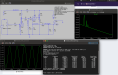
I went in a different direction with the simulating. If I use a 12AT7 (ECC81) high-mu triode for the first stage, and DC-couple that to a triode-wired 6V6GT (or equivalent) cathode follower, and finally wrap about 10dB of negative feedback around the circuit (R1 and R2), I get 0.035% THD at 1.414V peak (1V rms) output into a 300 ohm load.

The 'grass' along the bottom of the graph is at -135dB, which Adrian Immler's models show, but others don't.
H2 is almost -70dB and H3 is near -95dB.

I'm sure there will be objections to using negative feedback like this. Oh well...
NB:
One channel is shown. The power supply shows 1V of ripple superimposed (for modeling the PSU ripple rejection and circuit PSRR), and the 45mA current sink represents the other channel's current draw. You can ignore all that and just look at the DC voltages.
D2 is arc protection for the 6V6 to protect it from exceeding the cathode-to-heater voltage limit at power on.
D1 could be replaced by a 750 ohm resistor bypassed with 150uF.
The two channels combined draw 91mA from the B+ supply. Use a 150mA or higher rated power transformer so that it doesn't vibrate or buzz from the high value capacitors used to suppress power supply ripple.
C1 is a 240uF 265V film capacitor I got surplus. I think it's a motor run cap.
--
Code:
Harmonic    Frequency     Fourier     Normalized     Phase      Normalized
 Number       [Hz]       Component     Component    [degree]    Phase [deg]
    1       1.000e+03    1.413e+00    1.000e+00      179.60°        0.00°
    2       2.000e+03    4.982e-04    3.525e-04      -84.08°     -263.68°
    3       3.000e+03    2.673e-05    1.892e-05     -176.01°     -355.61°
    4       4.000e+03    1.105e-06    7.822e-07       90.56°      -89.04°
    5       5.000e+03    2.379e-07    1.683e-07       67.08°     -112.51°
    6       6.000e+03    5.782e-08    4.092e-08        8.53°     -171.07°
    7       7.000e+03    2.141e-07    1.515e-07       87.15°      -92.45°
    8       8.000e+03    4.376e-08    3.096e-08       15.18°     -164.42°
    9       9.000e+03    2.154e-07    1.524e-07       92.91°      -86.69°
   10       1.000e+04    3.540e-08    2.505e-08       19.48°     -160.12°
Total Harmonic Distortion: 0.035303%(0.035294%)
The 'grass' along the bottom of the graph is at -135dB, which Adrian Immler's models show, but others don't.
H2 is almost -70dB and H3 is near -95dB.
I'm sure there will be objections to using negative feedback like this. Oh well...
NB:
One channel is shown. The power supply shows 1V of ripple superimposed (for modeling the PSU ripple rejection and circuit PSRR), and the 45mA current sink represents the other channel's current draw. You can ignore all that and just look at the DC voltages.
D2 is arc protection for the 6V6 to protect it from exceeding the cathode-to-heater voltage limit at power on.
D1 could be replaced by a 750 ohm resistor bypassed with 150uF.
The two channels combined draw 91mA from the B+ supply. Use a 150mA or higher rated power transformer so that it doesn't vibrate or buzz from the high value capacitors used to suppress power supply ripple.
C1 is a 240uF 265V film capacitor I got surplus. I think it's a motor run cap.
--
Last edited:
Are you sure, that those parameters are correct?Also worth noting is the actual power requirements of the HD6XX:
0.7mA RMS, 0.2181V RMS, 0.2mW power.
If these are correct values, I don't understand why do you want to use KT66 with more than 40mA current. Not to mention that input signal peek at first stage would be about 35mV RMS.
@kward your design looks great, thanks for sharing! How'd you decide on 6H30 for your power tube? Thanks for your direct coupled design for the KT66, I'm having fun playing with it but I can't seem to get the distortion very low unfortunately.
@euro21 That's what the headphone power site says. As for why the KT66, I mean, I think I already said that I have some nice KT66 that I wanted to see if I could build a headamp for, and was inspired by Donald North and Feliks Audio designs (though those are production amplifiers for which I don't have the schematics, I wish I did). Maybe it's silly, I don' t know. Maybe for my first design I should try something more conventional like an EL84 to make a "better" TA84 instead.
@euro21 That's what the headphone power site says. As for why the KT66, I mean, I think I already said that I have some nice KT66 that I wanted to see if I could build a headamp for, and was inspired by Donald North and Feliks Audio designs (though those are production amplifiers for which I don't have the schematics, I wish I did). Maybe it's silly, I don' t know. Maybe for my first design I should try something more conventional like an EL84 to make a "better" TA84 instead.
(If I were sane I'd make my first from-scratch design something proven and well-known like a Morgan Jones Mini.)
I had some available 😏How'd you decide on 6H30 for your power tube?
@rongon could you post the asc of your amp? Thanks for sharing, looks interesting. Why do you like the 6V6 tubes? Did you pick the 12AT7 because it has more gain and therefore better for global negative feedback?
.asc attached
You may not have the same models I used, but you can substitute the standard Ayumi N. models, or whatever you like using. U1 is 12AT7 and U2 is 6V6.
I like 6V6 because its heater only requires 6.3V at 300mA, instead of 900mA for a 6L6 or KT66, or 1.5A for an EL34. It doesn't make sense to me to burn up 10 to 15 watts of power just to heat the tubes for an amp that only needs to make one-tenth of a watt of audio power per channel.
There is also a cute 9-pin Russian version of 6V6 called 6P1P, or Chinese 6P1.
Yes, I chose the 12AT7 for higher gain to drive the negative feedback loop, but still with enough plate current to avoid slew limiting into the input capacitance of a power triode. 6DJ8 would be a valid choice for that first stage too, but with lower permissible plate voltage. 12AU7 or 6FQ7 would work too, but with lower gain to drive the feedback loop, so likely higher THD in the output.
Attachments
Last edited:
For my design using the 6H30, I was not willing to compromise on some things, global feedback being one of them. I was willing to live with more distortion when using the headphones at the expense of having no global loop feedback, because the requirement was mostly using it as a line amp driving a power amp, but feedback was something I considered. You may not be able to achieve all your requirements simultaneously. You will likely need to compromise on something: a different topology, living with a little more distortion, changing output tube choice, adding an interstage transformer, adding some feedback, adding a transistor or op amp, etc, or a combination of those.Thanks for your direct coupled design for the KT66, I'm having fun playing with it but I can't seem to get the distortion very low unfortunately.
On a different note I just stumbled on this "Maple Tree Mellow Boy OTL amplifier" which I've seen no reviews of and have no idea how it sounds, but to their credit they put the schematic in the manual, and look at this:

So putting aside the power supply, this is the simplest headphone amp circuit I've ever seen. This is even simpler than the Crack. I'm kind of mesmerized by it. The actual unit seems to have a "mellowness" dial on the back that doesn't seem to be in the schematic that's supposed to make the sound "softer" or "crispier", but I'm not sure what that actually does or how it works. Wonder how it sounds?
Source: https://www.mapletreeaudio.com/manuals/OD-OTL6SL7-6336-Manual-V1.pdf
@rongon So this may have to do with me having to change the diode models (since I didn't have yours) or using different tube models or something, but on your design when I use the parameters I was using and feed 700mw into the circuit I get no gain (or even high negative gain) and high distortion.

So something not right there. ASC and tube models attached
So something not right there. ASC and tube models attached
Attachments
- Home
- Amplifiers
- Tubes / Valves
- OTL Tube headphone amp design with 12AU7 and KT66 tubes