You're probably well over max dissipation unless your screen voltage is low. Like WAY low. You are just simming this circuit for now, right? Otherwise you'll know what red-plating is all about.
Oh, this is definitely just a simulation at this point--as I said in the beginning there's a lot more I'd have to do before I'm ready to try building anything. Posting the designs here is part of the process of making sure I'm not, you know, red plating my tubes.
OK, when you removed or omitted the cap going to the KT-66 you dumped a bunch of +V from the driver plate onto the grid and that is what's making the idle current high even though you have cathode resistor biasing. It's a form of direct coupling which can work if it's designed right as you showed on the other post. But puting both together is another design art form

@mr_zener thanks for this! So using the AC trick it looks like the output impedance is only around 80ohms for most of the audible band:

However, a bigger problem, I think, is that your simulation has nearly 4% harmonic distortion. Of course, the main reason I don't want to use a 6080/6AS7 is because that's what the Crack uses and I wanted to do something different, and I picked the KT66 because I have them and like the sound (though admittedly I've only tried them in OTC amps so far, though apparently you can run the Feliks Euforia with KT66 tubes with an adaptor). How would one add global feedback to this design? Just run a line back from the output to the input?
@20to20 so adding a cap after the input tube using the value from mr_zener's schematic does bring the anode current down to a much more reasonable 60mV, though the THD goes up to 0.9% and the gain goes down (but only a little bit--seems like it's still around 13db). Seems not bad, though, something to play with.
Thanks to both of you for your help!
Last edited:
Basically yes, because it is an inverting amplifier.How would one add global feedback to this design? Just run a line back from the output to the input?
To implement NFB I first changed the 12AU7 to 12AX7 due to its much higher gain thus more to feedback for correction, the 12AU7 doesn't have enough gain for this.
It is now just over 0.6% THD. But involves a change of tube 🤔
Oooo... maybe this the reason to switch to the 6SN7 since that has higher gain as well. I'll play with it, thanks!
This might also relate to the idea of using two tubes in the first stage like Feliks does with their OTL amps. Maybe they just have two preamp tubes providing extra gain for their global feedback. (Would love to get my hands on the Euforia schematic and see how they do it.)
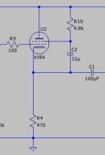
Latest experiment: drop the resistor on the KT66 grid (since we have the C3 capacitor there), and adjust the resistors on the 12au7. Not bad:

Getting rid of R3 made the distortion even lower

The main problem with this design is that at lower volumes it's fine, but if you turn the volume knob all the way up the anode current goes to like 100mw, which it turns out is over the power rating of the tube (which is 27 watts, and 100mw * 300V = 30 watts = explodey tube)
The main problem with this design is that at lower volumes it's fine, but if you turn the volume knob all the way up the anode current goes to like 100mw, which it turns out is over the power rating of the tube (which is 27 watts, and 100mw * 300V = 30 watts = explodey tube)
Attachments
Last edited:
That's what happens if there is no grid leak resistor (R3). There has to be a ground reference to bleed off charge that builds and give the signal voltage a complete path. It can be 100K if 250K is too big. There is a maximum value for the KT66, on the data sheet.
Calling a cathode follower an "output transformerless amp" always sounds kinda perverse to me. I mean, I know it technically qualifies as OTL, it just sounds somehow wrong in my head, like calling an oven a 'heater'!
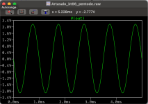
BTW, since you've got such a low-impedance load, you have an easy opportunity to run the KT66 in pentode mode rather than triode mode, by connecting the screen cap to cathode instead of ground. You don't see many pentode-mode cathode followers, it might be worth an experiment!
BTW, since you've got such a low-impedance load, you have an easy opportunity to run the KT66 in pentode mode rather than triode mode, by connecting the screen cap to cathode instead of ground. You don't see many pentode-mode cathode followers, it might be worth an experiment!
Attachments
Running the R10 to ground with a cap (and raising its value to the one in the mr_zener respin) actually reduces distortion in the model while increasing gain a small amount. Would love to know why. I'm pretty excited about how this is looking now.

Attached is also the updated asc
Attached is also the updated asc
Attachments
Shoot, if you crank the volume up on this design it'll also melt the tube. Gonna need some more work.
Making R5 50 ohms (closer to what Mr_Zener had) using Mr_Zener's 470 ohm value seems to keep the amp out of the danger zone.
Oh I just saw this, I’ll give it a try, thanks!Calling a cathode follower an "output transformerless amp" always sounds kinda perverse to me. I mean, I know it technically qualifies as OTL, it just sounds somehow wrong in my head, like calling an oven a 'heater'!
BTW, since you've got such a low-impedance load, you have an easy opportunity to run the KT66 in pentode mode rather than triode mode, by connecting the screen cap to cathode instead of ground. You don't see many pentode-mode cathode followers, it might be worth an experiment!
I'm trying to figure out how to automatically display the voltages on the nodes,
- Right click the node where you want the DC voltage to be displayed
- Select "Place .op Data Label"
Oh this worked! Thanks!
- Right click the node where you want the DC voltage to be displayed
- Select "Place .op Data Label"
The only problem is now I can't figure out how to limit the decimal places. The suggestion I found on Google said to open up the ASC file in a text editor, but when I do that it's indecipherable gibberish and not the kind of things that the Google result would suggest.
Attachments
- Home
- Amplifiers
- Tubes / Valves
- OTL Tube headphone amp design with 12AU7 and KT66 tubes