Also, the tubes definitely 'blow'/deteriorate/fuse/'boom'/fail in pairs, in the last case, one +160 and one -160.... hmmmmmmm
We are still waiting for some test results, oscillograms.
How much money did you set aside for replacing the 6080? I would implement some protection devices or circuitry, unless you don't care about the cost.
How much money did you set aside for replacing the 6080? I would implement some protection devices or circuitry, unless you don't care about the cost.
If it's not regulated - calculate the possible maximum voltages (ie measure current AC mains, the output from the PSU and heater, then look at your standard supply with the maximum ± variation - the UK is 230V ±10% so add transformer regulation on top and and that could be +15% or so if you have a non-regulated PSU.
Which ever way - given it's a intermittent and completely unknown (or at least the pop is), you need to work back methodically That may perhaps take a full 24 hours of monitoring to record the peak. However I wouldn't simply risk another set of tubes.
So: test the PS for both rails and heaters, monitor the AC input too. Then check the caps and tubes for each section, so you can say "yes that section has been tested" then move forward.
At each step you need to look at the schematic and think if the readings you have actually makes sense - voltage DC, AC peaks and along with the current. Check the schematic and the operating points to ensure you're not going grid positive at a possible peak of input or transient.
The 6080 has ±300V heater to cathode so it's unlikely you're going to get a failure from the heater unless, say the AC peak positive with the bias and the heater bias goes beyond that.
Personally I don't like serial heaters. If they don't warm up at the same rate, then it's a chance you one filament gets roasty but it sounds like they're failing in operation - so either something getting warm is leaking DC, or the transformer is shorting once it's warm or on a particular amount of current draw.
Trouble is, unless you're methodical and driven by the scope results vs the design, it's like playing battleships (where you're guessing the position of the other player's ships).
Bring it up slowly using a variac, and monitor the bias voltage+current while bringing up. Stop before the bias gets too hot for the tubes.
Did you consider this? This test would tell you a lot about how the amp is treating the tubes wrongly.
OK, I was to fast. You wrote that you'll proceed on Sunday, missed that.
Whatever you do, do not connect the pre-amp until you sort out the problem.
Whatever you do, do not connect the pre-amp until you sort out the problem.
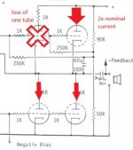
You might be witnessing two distinct failure modes as a result of a cascade. Since this looks like a totem pole style topology, a failure of one of the "top" tubes usually results in immediate failure of the second "top" tube, since it is now required to sink twice as much current. Apparently this runaway failure was a concern in early Futterman OTL amps utilizing this topology.
The wacky filament voltage could be taking out the first tube and the resulting over-current condition takes out the next tube (the fused cathode lead?). A well designed output stage should have some kind of protection or fuse in place to resist such a cascade. Could be why Tektron suspiciously has all but scoured the internet of any reference to this model...
The wacky filament voltage could be taking out the first tube and the resulting over-current condition takes out the next tube (the fused cathode lead?). A well designed output stage should have some kind of protection or fuse in place to resist such a cascade. Could be why Tektron suspiciously has all but scoured the internet of any reference to this model...
Attachments
Output stages separated work, it also allows the tubes to be adjusted independentently:

If the upper tube fails, then plate of the lower simply sees the cap. If the lower tube fails then the plate sees the cap.
A fuse is likely to blow after the event.. so a simple rail crowbar with something watching the output voltage.
If the upper tube fails, then plate of the lower simply sees the cap. If the lower tube fails then the plate sees the cap.
A fuse is likely to blow after the event.. so a simple rail crowbar with something watching the output voltage.
Last edited:
SPICE
Hi Guys,
I have a rough and ready schematic here (LTSPice) attached.
This was done VERY QUICKLY on my break so save the critiques it is what it is, it may not be my neatest work but it is what we have.
I have ran it in SPICE but takes a while.
If you see anything obviously (I know have alpha brain and cannot see anything) then let me know or amend as required.
Attachments
Hi Guys,
I have a rough and ready schematic here (LTSPice) attached.
This was done VERY QUICKLY on my break so save the critiques it is what it is, it may not be my neatest work but it is what we have.
I have ran it in SPICE but takes a while.
If you see anything obviously (I know have alpha brain and cannot see anything) then let me know or amend as required.
I put 400m ESR for the caps, 80m for the large electrolytic and 0.01ohm on the voltage sources, but after that:

You may want to setup the ESR for the caps you want to use.
Hi Nik
What results were you getting without the ESR.
It wouldn't settle enough to allow a bode plot. Where I've seen this before it's because the ESR/voltage sources need at least something in there.
Thanks Nick,
I could see the 80v Spike at the load.
The idea was not really to produce a simulation but I figured if I was going to make a schematic might as well use SPICE, was going to do it in Altium but then figured everyone has LTSpice or any other SPICE app.
I am going to take a look later and see what I can see with regards to the fault.
Thanks again Nick

125mA MAX plate accords the data sheet, I think it may have overshot this, that is the 6080, and around 60mA for the 12au7 from memory
Also the load is 200Ohm+SPEAKER, there is a 5w 200Ohm Resistor tied across the terminal of the speaker
1. Missing grid bias resistor at the input
2. R16 22k is too low and draw too much current, est value 100k
3. NFB phase of this LPT stage (U11, U12) is reversed.
4. R23, R15 cathode res 2.2k bias is about 3.8V is insufficient to out 80V drive.
5. NFB to this stage (U9, U10) is reversed
6. No grid bias resistor for grid supply (78V and -80V)
7. NFB to LTP stage value is too much, sensitivity is low.
I attach the version I edited that sim properly, but do repeat check on the above areas again.
Attachments
Hi Koonw,
The GBR 470k I missed
R16 is 22K
NFB reversed for you because you move input to from U12 to U11
R23 and R15 are 2.2k
Ditto
100K resistors grid bias on the grid supply - they were hidden on the power supply
The value are correct on the NFB to Long tail
I have checked the values again and they are all correct, I checked your version and it is not how it is in reality albeit your design does work.
I cannot comment on the original design as it Atillio's special number 1 OTL amplifier design.
An interesting discovery this morning, when I was looking at the amp, I lifted the 5.7Uf coupling cap and R14 (22K) was black! something has drawn a lot of current, looking at the circuit that leads to the output cap, just another little stinker to throw in.
Last edited:
The correction was based on your drawn schematic, I just comment that it's incorrect. I hope you only use it as a basis for reference. We don't know the actual circuit unless the designer publish it. As we don't find original circuit it's up to anybody guess. The photos you posted is helpful but not enough for us to duplicate the circuit on paper nor to double check for you.
- Home
- Amplifiers
- Tubes / Valves
- OTL Exploding tubes