Hmm oscope on the driver tubes without the 6080 present, leave for a couple of hours to record peak?
I think this is the next move, will take it to work a connect to my dso and see what occurs.
Will keep y’all posted!
Will keep y’all posted!
I'm not a tube guy, but can tube amps destroy themselves when bursting in oscillations?
I have *never* seen a valve's glass envelope shatter, in more than a half century, including in military transmitters, in a carillon struck by lightning where half of the eight 845s had melted innards and one holed envelope, or especially in any audio device.
To say that multiple octal-base glass valves burst through their envelopes simultaneously with the energy available from a commercial audio amplifier's power supply, well, let's just say it stretches credulity. "Pix or it never happened."
All good fortune,
Chris
1) I´ve been asking for pictures from day one.
2) IF filaments were wired for 6.3V and all in parallel, how come now each one has 24V? Does not make sense.
3) IF 4 x 6.3V filaments were wired in series and connected to a 24V tap, how come now each one has said 24V on its filaments? Does not make sense.
4) has anybody rewired filaments?
5) filament voltage is measured between pins 7 and 8 at each tube socket. HAS it been measured that way?
Lots of contradictory or insufficient data.
6) whn it worked for 2 hours, DID you measure filament voltage at each tube or just happily listened to Music without checking?
7) did all tubes blow or just a couple?
8) what does blow actually mean?
Cracked/flying glass?
Red/Orange/White hot plates?
Bright flash inside bulb but nothing else?
9) what´s the visible difference between a blown and an unblown tube?
Can you put examples side by side and show us the difference?
Probably have more doubts but answering these might clear something.
Good Morning JMFahey,
I can see from you post that you are all about the detail, I feel that we are kindred spirits in many respects, however............
Point one of your last post states "I've been asking for pictures from day one" and I fear that there has been a slight misrepresentation of the facts here.
I initially posted the original message 20 hours prior to your last post, now I accept that in terms of naming convention the day had in fact switched from Wednesday to Thursday, however I prefer to measure a day by a conventional 24hrs, and as such, we are still in day 1.
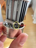
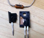
Now I have, within day one, attached the dissected tube image, I can verify that it is the upstand connected to the K1 pin, however, the once attached lead has now gone, I have no video evidence of this occurring however I think the image does empirically demonstrate the condition to be as told.
The 'event' which I have enveloped under the definition of the verb 'BOOM' or 'BLOW' was a large white flash which I presume to be ionised plasma (this is just my hypothesis given the conditions, my antithesis is that it was a marshmallow, I have yet to publish my work on this).
I do not have the specification for the amount go Torr inside of the tube, however I am just about at sea level where we live so we can assume an air pressure of 14.7psi outside of the tube.
I trust that the photographic evidence is of such quality you are able to deduce, as have I, that an amount of current greater than the failure tolerance of the material used to connect cathode to the pin has passed from the anode (or the grid) and as such, created a light show only rivalled by a Pink Floyd concert.
I am wondering if there is some inductance happening here, as the timescales seem to be odd, my gut is telling me that there is an issue with the driver stage and 6080 are paying the price. My money is on one of the caps have failed, however on the lcr they test fine, the voltage is low on the LCR, I am betting that they are not failing until they get some of the good voltage on them.
I have changed the driver tubes as well, so it is not that!
Thanks guys
I can see from you post that you are all about the detail, I feel that we are kindred spirits in many respects, however............
Point one of your last post states "I've been asking for pictures from day one" and I fear that there has been a slight misrepresentation of the facts here.
I initially posted the original message 20 hours prior to your last post, now I accept that in terms of naming convention the day had in fact switched from Wednesday to Thursday, however I prefer to measure a day by a conventional 24hrs, and as such, we are still in day 1.
Now I have, within day one, attached the dissected tube image, I can verify that it is the upstand connected to the K1 pin, however, the once attached lead has now gone, I have no video evidence of this occurring however I think the image does empirically demonstrate the condition to be as told.
The 'event' which I have enveloped under the definition of the verb 'BOOM' or 'BLOW' was a large white flash which I presume to be ionised plasma (this is just my hypothesis given the conditions, my antithesis is that it was a marshmallow, I have yet to publish my work on this).
I do not have the specification for the amount go Torr inside of the tube, however I am just about at sea level where we live so we can assume an air pressure of 14.7psi outside of the tube.
I trust that the photographic evidence is of such quality you are able to deduce, as have I, that an amount of current greater than the failure tolerance of the material used to connect cathode to the pin has passed from the anode (or the grid) and as such, created a light show only rivalled by a Pink Floyd concert.
I am wondering if there is some inductance happening here, as the timescales seem to be odd, my gut is telling me that there is an issue with the driver stage and 6080 are paying the price. My money is on one of the caps have failed, however on the lcr they test fine, the voltage is low on the LCR, I am betting that they are not failing until they get some of the good voltage on them.
I have changed the driver tubes as well, so it is not that!
Thanks guys
Attachments
my antithesis is that it was a marshmallow, I have yet to publish my work on this
😀
Since the connection between the cathode and the pin has melted, a lot of current has clearly passed through the tube. If it was my amplifier, I would fit a fuse on the anode on each tube before experimenting further. And buy a big pack of fuses. I would then connect a volt meter between anode and cathode on one of the tubes and another volt meter between grid and cathode and monitor the voltages when the amplifier is turned on. If you don't have two volt meters, go to the shop. It will be tricky to solve this blindfolded. 🙂
If the anode-cathode and grid-cathode voltages are OK and the tube still passes too much current then the heater to cathode insulation must have broken down. But, you wrote that the heaters were connected to ground so that shouldn't happen. To verify that the connection is still OK, measure the resistance between the heaters and ground.
If the anode-cathode and grid-cathode voltages are OK and the tube still passes too much current then the heater to cathode insulation must have broken down. But, you wrote that the heaters were connected to ground so that shouldn't happen. To verify that the connection is still OK, measure the resistance between the heaters and ground.
Pictures conjure up a mighty instantaneous blast under controlled conditions with the application of some super charged vacuum hardly leaving any sharp edges around the rim of the tube base!
Bias supply had been mentioned. Is it positive at some unfathomable magnitude?
Bias supply had been mentioned. Is it positive at some unfathomable magnitude?
Hej,
The quiescent voltage seems fine and the amp IS stable at this state (DSO with HV Probe this morning) I am going to remove all of the output tubes leaving just the 82's in place and take some control data.
I was not ballsy enough to load the output or connect a source as the bangs makes me wee a little and this could be embarrassing around normal folk.
I have also decided to create a schematic of the thing, I feel that we have all become invested in this, and my hope that an OTL expert would just point his/hers/zee/zim and other pronouns magic finger and piff paff puff fixed has turned into the reality of my over optimism is not analogous to real life.
I am now taking the view of this is just another SRPP with a little less iron and working like that.
It has a lot of DC coupling on it, I am going to start there, the control here is that the speakers were the same, the source changed, and that is when the trouble started, so although I have reverted to the old working condition of the 12AU7 preamp, it still revolves to the same condition BOOM (my definition) the plate resistor was within tolerance so I assume this is an issue on the grid, I need the schematic, I will then plug it into spice and see what happens.
I have the spec sheets for the tubes so I can get the resistances and the plates resistors etc, we know the tubes are good as I tested them on my trusty Mullard (on another note, I make the cards for these if you have one).
Great hearing from the Nordic brothers
The OP had restated that his initial use of the word "explode" was actually the vaporization of the internal cathode to pin link inside the tube. No glass shattering kaboom occurred.
In over 50 years of abusing tubes I have seen two where the glass shattered with considerable force, and a few more where it just cracked up and some pieces fell off.
In the early days of cheap Chinese tubes (1990's) I got a bulk pack box of 100 KT88's from Stan at ESRC for real cheap because "these are so bad that I can't sell them. They all blow up." I tested them by sticking them in pairs into a DIY 35 watt guitar amp that ran pretty conservatively for a KT88. A few worked good enough to use in amps at that power level, and 8 or 10 lived at the 100 watt per pair level and I still have some of them for use in experiments that could end badly. Most however either had obvious visual assembly issues, or had red spots on the plate at 20 watts or less of dissipation. Again poor assembly.
One tube erupted in a rather neat display of fireworks inside with matching sound effects in the speaker, so I just let it go on. The show lasted for about a minute before the tube shattered. Glass was scattered all over the insides of the amp, but the tube was mounted upside down in a combo amp with an internal speaker, so it got some serious shaking.
All other exploded or shattered tubes were results of operation FAR beyond normal conditions.
Tubes can crack or shatter when a serious overcurrent flows through a pin where is passes through the glass. A miswired socket on a Russian 6S19P forced all the current an 8 amp 6.3 volt transformer winding could deliver through one plate pin into the tube and another out of the tube. This scattered the glass all over the bench.
My biggest bang occurred while trying to curve trace a tube / mosfet pair with my HP6448B power supply operating at 650 volts. This supply is an old style 60 Hz switcher with 1000uF of output capacitance. When an error in judgement dumped all that stored energy into a mid sized TV sweep tube, it did literally explode.....and yes I have pictures.
There were actually two such dumm blonde experiments that ended badly. In the first case the tube simply flashed brightly, the glass cracked, and a few pieces fell to the bench nearby. You can see that the crack started where the plate pin (pin 7) passes through the glass. I assumed that the mosfet failed, so I put in a bigger fet and tried again. This time there was a much bigger bang with scattered glass and mosfet parts all over the bench and floor.
The plate pin was permanently welded into the socket. The rod from the plate to the glass is visible in the picture, but most of the link that passes through the glass was vaporized causing the glass to shatter. Autopsy revealed a tube arc resulting an a small loss of cathode coating. It is still not known whether the tube or the mosfet failed first. If the fet shorted (the usual failure mode) it would remove all bias from the tube resulting it trying to eat all the stored energy in the power supply.
This was a tube rated at 24 watts plate dissipation. I was planning to test it up to 50 watts or more, but a dumm judgement error actually applied 350 watts. I have seen 40 watt tubes eat over 600 watts for a few mS, so I still believe that the fet failed first. A subsequent test on a similar tube alone showed that it could indeed survive brief tests at over 100 watts, but I did not go past 100 Watts.
I have *never* seen a valve's glass envelope shatter, in more than a half century
In over 50 years of abusing tubes I have seen two where the glass shattered with considerable force, and a few more where it just cracked up and some pieces fell off.
In the early days of cheap Chinese tubes (1990's) I got a bulk pack box of 100 KT88's from Stan at ESRC for real cheap because "these are so bad that I can't sell them. They all blow up." I tested them by sticking them in pairs into a DIY 35 watt guitar amp that ran pretty conservatively for a KT88. A few worked good enough to use in amps at that power level, and 8 or 10 lived at the 100 watt per pair level and I still have some of them for use in experiments that could end badly. Most however either had obvious visual assembly issues, or had red spots on the plate at 20 watts or less of dissipation. Again poor assembly.
One tube erupted in a rather neat display of fireworks inside with matching sound effects in the speaker, so I just let it go on. The show lasted for about a minute before the tube shattered. Glass was scattered all over the insides of the amp, but the tube was mounted upside down in a combo amp with an internal speaker, so it got some serious shaking.
All other exploded or shattered tubes were results of operation FAR beyond normal conditions.
Tubes can crack or shatter when a serious overcurrent flows through a pin where is passes through the glass. A miswired socket on a Russian 6S19P forced all the current an 8 amp 6.3 volt transformer winding could deliver through one plate pin into the tube and another out of the tube. This scattered the glass all over the bench.
My biggest bang occurred while trying to curve trace a tube / mosfet pair with my HP6448B power supply operating at 650 volts. This supply is an old style 60 Hz switcher with 1000uF of output capacitance. When an error in judgement dumped all that stored energy into a mid sized TV sweep tube, it did literally explode.....and yes I have pictures.
There were actually two such dumm blonde experiments that ended badly. In the first case the tube simply flashed brightly, the glass cracked, and a few pieces fell to the bench nearby. You can see that the crack started where the plate pin (pin 7) passes through the glass. I assumed that the mosfet failed, so I put in a bigger fet and tried again. This time there was a much bigger bang with scattered glass and mosfet parts all over the bench and floor.
The plate pin was permanently welded into the socket. The rod from the plate to the glass is visible in the picture, but most of the link that passes through the glass was vaporized causing the glass to shatter. Autopsy revealed a tube arc resulting an a small loss of cathode coating. It is still not known whether the tube or the mosfet failed first. If the fet shorted (the usual failure mode) it would remove all bias from the tube resulting it trying to eat all the stored energy in the power supply.
This was a tube rated at 24 watts plate dissipation. I was planning to test it up to 50 watts or more, but a dumm judgement error actually applied 350 watts. I have seen 40 watt tubes eat over 600 watts for a few mS, so I still believe that the fet failed first. A subsequent test on a similar tube alone showed that it could indeed survive brief tests at over 100 watts, but I did not go past 100 Watts.
Attachments
Guys,
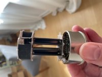
The tube I uploaded was not in this condition when it happened, I delicately removed the glass to preserved the internals.
I used a diamond wheel for most of it and then the rest just fell away
Kiitos
The tube I uploaded was not in this condition when it happened, I delicately removed the glass to preserved the internals.
I used a diamond wheel for most of it and then the rest just fell away
Kiitos
Well, I am a Tech, and I detailed all the tests I would make if it were on my bench.Good Morning JMFahey,
I can see from you post that you are all about the detail,
Plus others which would be called for (or not), depending on results.
Since it´s over 12.000 km away, I am asking you to test and look in my name 🙂
As of "since day one" don´t read into it more than it means, nor grab a clock and a calendar, it´s an "idiom", a way to speak portraying an idea.
From Merriam Webster Dictionary:
🙂Definition of day one
: the first day or very beginning of something
Back to the Tech issues:
Maybe. 😕attached the dissected tube image,.... it is the upstand connected to the K1 pin, however, the once attached lead has now gone ..... I think the image does empirically demonstrate the condition to be as told.
I see a bottle less tube and a couple wires but can´t notice if there "should" be an extra one.
My asking for a picture was more about shattered glass flying all over the place, implicit in the word "boom!!!" or "exploding" 😱 only now you say it was a "flash", a much milder event.
OK.The 'event' which I have enveloped under the definition of the verb 'BOOM' or 'BLOW' was a large white flash
No need for that.which I presume to be ionised plasma
Power being proportional to square of voltage, applying 24V, 4X the intended 6.3V means 16X the dissipated power, well enough to vaporize a filament, create a bright flash, etc.
Thanks but outside pressure is irrelevant, I´m interested in "vacuum" or gas contamination, what do the silver getters look like?I do not have the specification for the amount go Torr inside of the tube, however I am just about at sea level where we live so we can assume an air pressure of 14.7psi outside of the tube.
Well, as mentioned above I see a few wires, no evidence of a missing one unless I have another same model tube side by side, nor molten metal globules or spatter, so I´ll have to believe you one wire fell out.the photographic evidence is of such quality you are able to deduce, as have I, that an amount of current greater than the failure tolerance of the material
No, no driver signal will cause filaments to explode, orders of magnitude too weak for that, I suspect the 24V present and how/why that happened so now let´s focus on that.I am wondering if there is some inductance happening here, as the timescales seem to be odd, my gut is telling me that there is an issue with the driver stage and 6080 are paying the price.
Please do the filament voltage and wiring tests I suggest above.
Can´t imagine a mechanism by which a shorting +V cap can make 6V filaments to explode en masse.My money is on one of the caps have failed, however on the lcr they test fine, the voltage is low on the LCR, I am betting that they are not failing until they get some of the good voltage on them.
No, see above, please do the filament voltage tests.I have changed the driver tubes as well, so it is not that!
Measure voltage present at each 6080 filament, I think filament pins were 6&7 but please recheck datasheet, don´t trust my memory.
Good luck.
Last edited:
Guys,
The tube I uploaded was not in this condition when it happened, I delicately removed the glass to preserved the internals.
I used a diamond wheel for most of it and then the rest just fell away
Kiitos
Bjorn, there are still a lot of unanswered questions from JMF that are necessary to get us any idea in which direction to look. You seem to do 'diagnostics' in a very chaotic way.
I will refrain from thinking about this after there is more info, but maybe somebody else stumbles on something that helps.
Life is too short!
Jan
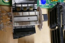
Your amp has bipolar supply of +-160V, and a blocking cap in the output. There are 2 tubes each on top and bottom bank. Assume that one of the top tube has developed an arc, it's dead short between plate and cathode, so the cathode of this tube is now at plate potential of +160V, this immediately blow one or all the tubes: 2 at the bottom and one more from top, a total of 4 tubes. By same logic all tubes will be blown when one of tubes in either bank develop an arc. The current just sink to ground, blown open any conductor not up to rating. So maybe you should install fuses and cathode resistors to limit the current flows. Just my option.
John Broksie’s OTL push pull section uses discrete pairs as it makes it easier to bias and should one arc, the only other tube of the pair will feel the current flow.
As I said. Run without and check the driver voltages over a period. This shows if there’s a problem grid wise, the othe option is that the power supply is doing the same peak test.
With a connected set of output tubes, it only takes one valve to provide an imbalance.
I can’t see if the output tubes in the bottom are fixed bias or not..
What people don’t say is that a large psu cap with an output cap can easily result in massive current spikes.
Last edited:
I experimented with the Bruce Rozenblit otl amp a long time ago but my layout was poor and it had LF instability issues. Some 6080s did end up popping. People have mentioned that the 6AS7 is more stable for otl applications but that might be anecdotal evidence.
Next test try a current limiter in the power supply. As an example, use a filament bulb in series to the primary of the power tranformer. To do such a thing easily, get a bulb socket with short pieces of isolated cables and wire it to the fuse or power swich, removing the fuse or keeping the switch in the off condition. So all primary current must flow through the lamp and any anomality will be reflected as an increase of the lamp bright. Use a lamp between 2 to 5 times the power the amp. normally drain.
Under normal conditions, the first time you power the amp you will see a large flash on the lamp until the heaters run their normal temprature and caps in the PSU becomes charged. Tje amp, now must reduce its light to a small red filament slightly vissible. If under any circumstance the light increases, then some is going wrong and you can safely shut down the amp.
I made it in a more suitable form for my habitual jobs.
When I was a kid the 5U4 "low voltage rectifier" as it was called in the Sam's Photofact used to occasionally explode in our B/W Magnavox portable TV. It literally would explode when you switched on the set during warm up. My dad would just put in a new one. I always wonder its cause, now 55 years later I kind of suspect it may have been a bad reservoir cap, who knows. My dad would cuss when it happened then I knew Id have to take that walk to the drugstore while he was digging out the glass and tube base. I remember the drugstore sold RCA tubes, so they were good tubes. The tubes in that set were on a vertical chassis, maybe a DH rectifier Filament sagged, who knows.
Last edited:
Guys,
First off, thanks for all your responses, they are all appreciated, I realise that I may cluster bomb my responses with pointless comedy, but it has its place, and this should really be a recreational pursuit, amongst similar minded people.
I have not performed anymore chaotic diagnostics as yet, 2 lunatics children and 2 Akita dogs and an ultra efficient wife demand more time than I have, but I will do on Sunday.
I am going to dig my Morgan Jones book out, I am sure he had a whole section on OTL, maybe there is a eureka moment there, but like I say if there is a DC blocking issue, and somehow the plate voltage of the 82 is making its way to the 6080, this is baaaaaad, max DC on the plate of 6080 is 250v (Ratheon spec sheet) and I think the plates on the 82s is >300VDC, I will annotate a schematic and write I and V from math then from readings, there is a lot of DC coupling in this beast, so it may take me a while/loss of motivation.
Kitos
- Home
- Amplifiers
- Tubes / Valves
- OTL Exploding tubes