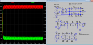
Your sim. nicely illustrates the way the a 1K resistance for R1 helps to protect the speaker in the event of a catastrophic short-circuit in an output tube. Note, by the way, that the capacitors C2, C4, C6 and C8 will get about 150V + 150V = 300V (or more, in fact, under the relatively light loading) across them in this fault condition. So one should design to allow for this. (And likewise for C1, C3, C5 and C7, since the fault could instead be a short-circuit of the lower tube.)No, I use 24V DPDT completely sealed relay, with 8A/250v switching capacity. No problems over the years, and I have several amps some are under construction but due problems with questionable brand e-cap in PSU, I need to buy some other brands for trial basis. There is no need to build the cutout unit on board as there some ready make unit can be used instead. My unit will cutout when there is more than _+2V offset, but will resume after 15s or so for minor fault, it wouldn't resume if the fuse is blown happened in a major fault. When first start, it senses the DC voltages from soft start unit, and connect the speaker when the delay timing is reached (< 5mins). Then it's connected to output, convert AC signal to DC for cutout.
Attached also shows how 1k resistor can protect the speaker as in original design but also with remake sch, but unfortunately the sim will show that it still has some offset in the output (<50mV), not sure it's corrected or not by DC servos.
In the latter sch, I no long used HT 500V, but 320V by grounding it directly instead stacking on top of +170V.
There is an interesting article by Rod Elliott that includes some discussion about arcing issues in loudspeaker protection circuits using mechanical relays; see https://sound-au.com/project33.htm . As seen in your sim., if one were taking R1 to be about 0 ohms and depending upon a cutout relay to protect the speaker, the contacts would need to break a DC current of order a few amps or so, with a voltage of order 150V when the contacts separated. He remarks that "there is no common relay known that can break a 70V DC arc at a current of more than a few hundred milliamps at most." The arcing problem grows non-linearly greater with higher voltages, so at 150V it could be pretty severe. It would undoubtedly lessen the risk if the relay switches the speaker terminal to ground when it trips, as in his figure 2, for example. Since you said you are using DPDT relays I guess this is what you are doing? Of course if a catastrophic fault of the kind one wants to guard against has never in actuality occurred in a specific amplifier, one could indeed go for years without ever encountering the potential arcing problem.
Last edited:
If you take into account internal resistance of copper winding (4 Ohms in the sim) of the power transformer, AC side voltage would drop as current will be limited by the copper winding. so that about 1/2 of 150V or 75V and 9 Amp across the speaker. But I feel is a lot of spark is due to high current discharge from e-capacitor, some sort of positive resistance PTR should be used (to replace R4/R5 0.1 ohms) to further limit the current from cap discharge in case of short circuit. Beside the relay contact is never subject to short for long for about few mili-secs, it would open at just +-2V! That is why a proper design cutout unit is faster and safer than the 1k protection resistor one taken so much pride of.
Attachments
Last edited:
I doubt there is any "ideal" way to guard against a sudden, catastrophic tube failure. The various methods that have been discussed all have their pros and cons. The approach taken by Tim Mellow with the 1Kohm resistor between the transformer centre-tap and ground has the merit of simplicity, and not requiring any active protection mechanism to activate at the moment of the failure. It is important, though, to use higher voltage ratings for the power supply capacitors than what is stated in the Tim Mellow Audio Express article, in order to ensure that they are not subjected to substantial over-voltages in the event of the tube failure. The "floppiness" of the floating mid-point of the power supplies, inherent to this approach, is a bit inelegant, though. Especially if both the left and the right channels are being run from the same power supplies.If you take into account internal resistance of copper winding (4 Ohms in the sim) of the power transformer, AC side voltage would drop as current will be limited by the copper winding. so that about 1/2 of 150V or 75V and 9 Amp across the speaker. But I feel is a lot of spark is due to high current discharge from e-capacitor, some sort of positive resistance PTR should be used (to replace R4/R5 0.1 ohms) to further limit the current from cap discharge in case of short circuit. Beside the relay contact is never subject to short for long for about few mili-secs, it would open at just +-2V! That is why a proper design cutout unit is faster and safer than the 1k protection resistor one taken so much pride of.
One should perhaps be a bit careful about your observation of the 72V across the speaker, since your sim. is showing what happens if the power is turned on with the tube short-circuit already in place, so the voltage builds up to 72V from zero at time=0. If the tube failure occurs while the amplifier is running, the full 150V will slam into the loudspeaker at the instant of the short circuit occurring (through of course the capacitor will partially discharge fairly quickly). In the event of such a catastrophic failure, the time between when the speaker has only 2V across it and when it has 150V across it will presumably be a matter of only a few tens of microseconds; it will have happened long before the relay could trip. Still, if one follows the Rod Elliott scheme in which the relay not only disconnects the speaker from the amplifier output but also grounds the speaker terminal when the protector trips, then even if (or when) the arcing occurs as the relay trips, the speaker itself should be held to ground voltage by the time the contacts of the relay have switched across.
Mosfets are sometimes used in place of mechanical relays for speaker protection, in the case of powerful solid-state amplifiers. This not only gets around the DC arcing problem, but also the protection operates much more quickly than mechanical relays ever could. This might be an approach worth considering, I feel.
PTC can limit the current, why no one bother?? My relay is fine even after several major shorting, I do not have PTC in use. The chances are that the when there is a short it's either the e-cap or output tube that comsume and dissipated within themselves (e.g exploded) before it can even pass to the speaker. One rail and power fuse is blown that is all. This has nothing to do with startup observation however, energy / power in or connection to a shorted component in itself is self consumed whether 150V or 75V. The idea is the copper resistance limit the current and voltage, try to to reduce it to 1 ohm, the voltage/ current shoot up, so your logic is flaw?
Last edited:
That doesn't seem to conflict with anything I was saying. I'm not sure why you are saying the logic could be flawed.The idea is the copper resistance limit the current and voltage, try to to reduce it to 1 ohm, the voltage/ current shoot up, so your logic is flaw?
Yes, if i were to use 1 ohm or copper resistance, the result HT is 150V, now no difference between startup or not. Never mind I understand what you.
i used output coupling capacitors and that took care of speaker safety no audible hit to sound quality....i did not use the 1k ohm resistor in the psu...
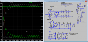
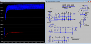
This is another snapshot that should explain the working principle of cutout relay. As shown the current and voltage in the speaker starts from 0, when the HT is +-150V, and ends with about +75V when the upper tube is shorted. So indeed it's quite a slam of current, but we make the relay to respond fast enough before current get too large (which also depends on speaker elements). This is about all from me on the protection, I will find PTC model in future to further improve it if necessary.
Attachments
Do you have any problem? The current in the speaker is quite similar to 1k resistor.i used output coupling capacitors and that took care of speaker safety no audible hit to sound quality....i did not use the 1k ohm resistor in the psu...
Attachments
I think you are not really simulating the condition that is of principle interest here. It seems t ome you are showing what happens if there is a pre-existing fault condition (represented by RT=1ohm across the upper tube) at the time the amplifier is switched on. As seen in your plot, the current through the speaker starts at zero, and ramps up as the power supply capacitors get charged up by the rectified AC supplies.This is another snapshot that should explain the working principle of cutout relay. As shown the current and voltage in the speaker starts from 0, when the HT is +-150V, and ends with about +75V when the upper tube is shorted. So indeed it's quite a slam of current, but we make the relay to respond fast enough before current get too large (which also depends on speaker elements). This is about all from me on the protection, I will find PTC model in future to further improve it if necessary.
However, the case of principle interest is when the amplifier is already running, and then the fault develops. Thus at the time t=0 when the fault begins (RT suddenly goes to 1 ohm), the capacitors C1, C3, C5 and C7 will already be charged up to 150V and will suddenly discharge into the speaker load Rspk, in series with RT1 and R2. (And, for the capacitors C1 and C3, there is the very small resistor R4 as well.) Thus, at the onset of the fault, at time t=0, we can see that the current through the speaker will begin at about 150/(1+1+8), i.e. about 15 amps. Even if we neglect the fact that the capacitors will be recharged in pulses ever 8 milliseconds or so by the AC from the power transformers, the voltage at t=15 milliseconds will still be about 103V (governed by the RC time constant of of the capacitors and the 10 ohm load resistance). So at this moment, when the relay is opening, it will need to break a DC voltage of order 100V with about 10 amps flowing. That can result in quite an arc.
Nice calculation! (better than Spice?) Have a look, how can you leave out the current about 1A through the lower tube when the upper tube is shorted? I can't blame you I should send you all snapshots so you can not overlook something. So final current =10A-1A=9A, wouldn't it be correct now?
My intention is to warn DIYer to note of potential danger, and so to avoid or persuade further never meant to be end to a solution. So far you write a lot but no diagrams how about a few Spice snapshots? I love to hear how you would simulate it? The start point is no fault condition (Rt1=10Meg), follow by a fault condition RT1=1, do you see this? The 2 conditions already met, I can't see else is needed. Never mind I have covered enough for this subject start few years back, unless there is still something serious to be addressed.
.step param RT1 list 1 10Meg
Attachments
Last edited:
Look at snapshot of this post # https://www.diyaudio.com/community/...y-tim-mellow-with-4-6c33c.175247/post-6956349So at this moment, when the relay is opening, it will need to break a DC voltage of order 100V with about 10 amps flowing. That can result in quite an arc.
I neglected the current through the lower tube because it has a relatively small effect on what is happening. If it is agreed that the cutout relay is going to trip at about 15 milliseconds after the fault develops, then what matters as far as the relay operation is concerned is what happens during those all-important 15 milliseconds leading up to the tripping of the cutout. As I was saying, at t=0, the instant the fault appears, there will be about 15 amps passing through the speaker, falling somewhat to around 10 amps or so at t=15 milliseconds. A correction of order 1 amp or so it pretty small beer.Nice calculation! (better than Spice?) Have a look, how can you leave out the current about 1A through the lower tube when the upper tube is shorted? I can't blame you I should send you all snapshots so you can not overlook something. So final current =10A-1A=9A, wouldn't it be correct now?
My intention is to warn DIYer to note of potential danger, and so to avoid or persuade further never meant to be end to a solution. So far you write a lot but no diagrams how about a few Spice snapshots? I love to hear how you would simulate it? The start point is no fault condition (Rt1=10Meg), follow by a fault condition RT1=1, do you see this? The 2 conditions already met, I can't see else is needed. Never mind I have covered enough for this subject start few years back, unless there is still something serious to be addressed.
.step param RT1 list 1 10Meg
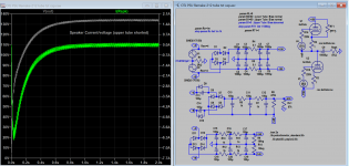
But that snapshot is not a simulation of what happens when the fault develops while the amplifier is already running. It is a simulation of what happens if the amplifier is switched on with the fault condition already in place.Look at snapshot of this post # https://www.diyaudio.com/community/...y-tim-mellow-with-4-6c33c.175247/post-6956349
No Chris, it's 0A at 0s instant not 15A, <5A at <15ms, and 9A > 200ms. Do look at snapshot again? 1A less or bypass is lot to me. The solution is to act fast when the current is still very low, simple like.
As in my previous post, your snapshot is not showing a simulation of what happens if the fault develops while the amplifier is already running.No Chris, it's 0A at 0s instant not 15A, <5A at <15ms, and 9A > 200ms. Do look at snapshot again? 1A less or bypass is lot to me. The solution is to act fast when the current is still very low, simple like.
Really? Then how come I bother to use 2 conditions: 1 for no faulty, 10Meg for normal condition. I would agree if only faulty condition.But that snapshot is not a simulation of what happens when the fault develops while the amplifier is already running. It is a simulation of what happens if the amplifier is switched on with the fault condition already in place.
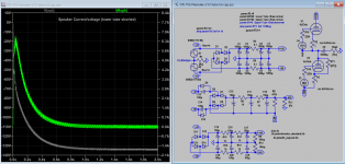
If the amplifier is running, there is 150V across that upper capacitor bank. At the instant the fault develops, you essentially have a 10 ohm resistor (comprising RT=1 ohm, R2=1 ohm and Rspk=8 ohm) connected across the capacitor bank. Therefore, the instantaneous current will be 15 amps, passing through the speaker. This will start to decay as time passes, but it will still be arounf 10 amps or so after 15 milliseconds. It is simply not possible for there not to be about 15 amps flowing at the instant the fault develops. It is just ohm's law.Really? Then how come I bother use 2 conditions: 1 for no fault, 10Meg for faulty condition. I would agree if only faulty condition.
Since your simulation doesn't show that, I would suspect that there is something amiss with how you have set up the conditions.
I'm not familiar with using step parameters in LTSpice, but having done a quick Google search, I can make speculation about what might be amiss. Doesn't the simulation restart from scratch for each of the choices of the stepped parameter? That seems to be what happens in examples I Googled. So when it runs the simulation with RT1=1 ohm (which in fact is in any case the first choice of the step parameter RT1 in your list?), wouldn't it therefore be showing what happens if you power up the circuit with RT set to 1 ohm? That certainly seems to be consistent with what your plots are showing; the current through the speaker builds up from zero.Really? Then how come I bother to use 2 conditions: 1 for no faulty, 10Meg for normal condition. I would agree if only faulty condition.
But that is definitely not what would happen if the power supplies were already charged up and then RT1 was abruptly set to 1 ohm. In this case (the actual fault condition one wants to study), the capacitors must necessarily dump that huge current of order 15 amps through the speaker at the instant when RT1 abruptly goes to 1 ohm.
- Home
- Amplifiers
- Tubes / Valves
- OTL designed by Tim Mellow with 4 6C33C?