This is not possible because using a single input tube the output signal is out-phase with input so global feedback cannot be connected.
I have also simulated it to confirm this.
---------------------------------------------------------
I can share with all the simulation files, uploading now ....
http://www.audiodesignguide.com/otl/Sim/
Only .asc and .inc files are necessary.
In some case is necessary overwrite the standard lib in LTspiceIV/lib/sym.
I can help all to understand how to use the freeware LTspice simulator.
Last edited:
You are right ! , it was my mistake !
Since I omitted the fact that your OTL output power stage is driven in Inverted Futterman mode .
Regards !
Since I omitted the fact that your OTL output power stage is driven in Inverted Futterman mode .
Regards !
Futterman variation - 2sk170, 12ax7, 12au7
Power 50W with 0.7% THD with only 0.5Vrms input
Global feedback 19dB, Rout = 0.5ohm (47Kohm / 1K)
Global feedback 18dB, Rout = 0.6ohm (56Kohm / 1K)
Global feedback 17dB, Rout = 0.7ohm (68Kohm / 1K)
Driver stage with one 450VDC
Freq. range 0.3Hz to 1MHz at -3dB
Power 50W with 0.7% THD with only 0.5Vrms input
Global feedback 19dB, Rout = 0.5ohm (47Kohm / 1K)
Global feedback 18dB, Rout = 0.6ohm (56Kohm / 1K)
Global feedback 17dB, Rout = 0.7ohm (68Kohm / 1K)
Driver stage with one 450VDC
Freq. range 0.3Hz to 1MHz at -3dB
Attachments
DC coupled OTL - version 1
Power 50W with 1 % THD with only 1Vrms input
Global feedback 17dB, Rout = 0.7ohm
Driver stage with one -300VDC and -15V
Freq. range DC to 1.8MHz at -3dB
-----------------
based on this design but more simple, I have add current mirror
http://www.audiodesignguide.com/otl/JPfig11.pdf
Power 50W with 1 % THD with only 1Vrms input
Global feedback 17dB, Rout = 0.7ohm
Driver stage with one -300VDC and -15V
Freq. range DC to 1.8MHz at -3dB
-----------------
based on this design but more simple, I have add current mirror
http://www.audiodesignguide.com/otl/JPfig11.pdf
Attachments
DC Coupled OTL - version 2
Power 50W with 0.3 % THD with only 0.7Vrms input
Global feedback 29dB, Rout = 0.05ohm
Driver stage with one -400VDC and -15V
Freq. range DC to 1MHz at -3dB
---
based on this design but more simple
http://www.audiodesignguide.com/otl/KANEDA01.JPG
-----------------------------------------------------------------------
ATTENTION: all the DC coupled projects must be tested with extreme care because these are only simulations
Attachments
Dynamic current generators - version 1
Power 50W with 0.5 % THD with only 0.7Vrms input
Global feedback 20dB, Rout = 0.7ohm
Driver stage with one 300VDC and -15V
Freq. range 0.1Hz to 1MHz at -3dB
Like for the previous DC coupled versions the pair of D3a generate a perfect symmetrical signal also if the reference voltage is different (better than Futterman).
Attachments
Last edited:
In the last design, both D3A have a different supply voltage. 300 V for one and 450V for the other. The schematic needs a slight correction...
Yes, the Dynamic current generators - version 1 can work with 300V and 400V, always the same result
The Dynamic current generators version 1, the DC Coupled OTL version 2 and version 3 drive the output tubes with a pentode so the open loop frequency band is limited to 100-150KHz.
I am sure that these will give very low performances in slew rate mesuarements.
I am sure that these will give very low performances in slew rate mesuarements.
Hybrid OTL - simple and good
Power 50W with 0.7% THD with 0.7Vrms input
Global feedback 19dB, Rout = 0.7ohm (33K / 1K)
Driver stage with 300V and -15V
Freq. range 0.1Hz to 3MHz at -3dB
Open loop frequency band 200KHz, Slew rate about 100V/us
This give the best symmetrical output wave because the transistor work better like dynamic current generator.
Attachments
Last edited:
Slew rate
Dynamic current generators - version 1
--- Slew rate about 60V/us
DC Coupled OTL - version 3
--- Slew rate about 15V/us
Technics configuration version 2
--- Slew rate about 53V/us
Futterman variation - version 2
--- Slew rate about 77V/us
Hybrid OTL - simple and good
--- Slew rate about 100V/us
Dynamic current generators - version 1
--- Slew rate about 60V/us
DC Coupled OTL - version 3
--- Slew rate about 15V/us
Technics configuration version 2
--- Slew rate about 53V/us
Futterman variation - version 2
--- Slew rate about 77V/us
Hybrid OTL - simple and good
--- Slew rate about 100V/us
Last edited:
ATTENTION
The max VCE for the MJE350 is 300V so it cannot be used in the real circuit.
I have found the PBHV9050Z
Ptot = 700mW
Ft = 50MHz
Vceo = 500V
Ic max = 0.25A
but in some case are necessary 10 or more devices in parallel
The max VCE for the MJE350 is 300V so it cannot be used in the real circuit.
I have found the PBHV9050Z
Ptot = 700mW
Ft = 50MHz
Vceo = 500V
Ic max = 0.25A
but in some case are necessary 10 or more devices in parallel
Last edited:
Full solid state driver
Just because others have done it, I present here a driver stage for otl completely solid state.
Power 50W with 0.5% THD with 1Vrms input
Global feedback 18dB, Rout = 0.7ohm (22K / 1K)
Driver stage with only 230V and -15V
Freq. range DC to 3MHz at -3dB
Slew rate about 22V/us
Just because others have done it, I present here a driver stage for otl completely solid state.
Power 50W with 0.5% THD with 1Vrms input
Global feedback 18dB, Rout = 0.7ohm (22K / 1K)
Driver stage with only 230V and -15V
Freq. range DC to 3MHz at -3dB
Slew rate about 22V/us
Attachments
Simulation results
Circlotron
- It is not possible use this configuration because it need four anodic power supply so another 1KW transformers (2 x 120V * 4A).
- The output current supported by any output device is the same of Futterman
- The output impedance is more high than Futterman and it can be compesated only with higher global feedback (about 3dB more)
Technics configuration version 2 - new simple
- It use a second feedback loop to conpensate the voltage gain of the lower output tubes with anode output.
- This is the less symmetric configuration
- Only 3 tubes and 2 stages with a single capacitor on the signal path
- Good Slew rate
- Driver stage with only one 400VDC and -15V
Futterman variation - version 2
- The output tubes are driven by a phase shifter connected to the amplifier output instead of ground to change the reference of the signals to have both tubes like a cathode follower.
- This need 3 stages, 2 voltage amplifier stages + phase shifter and 2 capacitors on the signal path
- The phase shifter drive with different output impedance the output tubes so this is not very symmetric configuration
- Good slew rate about 77V/us
- Strange use of 1/2 12AX7 and 1/2 12AU7 for each channel
- It need a higher power supply near to 450V
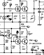
Futterman variation - 2sk170, 12ax7, 12au7
- This add a Jfet to reduce to only 2 stages and complete 2 tubes
- A single capacitor on the signal path
DC Coupled OTL - version 2 and 3
- These versions use a negative power supply to drive directly the output tubes
- It is necessary to use only solid state in input stage
- The pentode generate a perfect symmetrical signal also if the reference voltage is different but the output tubes are driven with high impedance so slew rate very bad
Hybrid OTL - simple and good
- This version use the transistor to generate a perfect symmetrical signal also if the reference voltage is different
- The driver is created with only 2 stage, a pair of jfet, 1 tube 12AX7 and 4 transistor used as current mirror
- This give the best slew rate and the larger frequency band
Circlotron
- It is not possible use this configuration because it need four anodic power supply so another 1KW transformers (2 x 120V * 4A).
- The output current supported by any output device is the same of Futterman
- The output impedance is more high than Futterman and it can be compesated only with higher global feedback (about 3dB more)
Technics configuration version 2 - new simple
- It use a second feedback loop to conpensate the voltage gain of the lower output tubes with anode output.
- This is the less symmetric configuration
- Only 3 tubes and 2 stages with a single capacitor on the signal path
- Good Slew rate
- Driver stage with only one 400VDC and -15V
Futterman variation - version 2
- The output tubes are driven by a phase shifter connected to the amplifier output instead of ground to change the reference of the signals to have both tubes like a cathode follower.
- This need 3 stages, 2 voltage amplifier stages + phase shifter and 2 capacitors on the signal path
- The phase shifter drive with different output impedance the output tubes so this is not very symmetric configuration
- Good slew rate about 77V/us
- Strange use of 1/2 12AX7 and 1/2 12AU7 for each channel
- It need a higher power supply near to 450V
Futterman variation - 2sk170, 12ax7, 12au7
- This add a Jfet to reduce to only 2 stages and complete 2 tubes
- A single capacitor on the signal path
DC Coupled OTL - version 2 and 3
- These versions use a negative power supply to drive directly the output tubes
- It is necessary to use only solid state in input stage
- The pentode generate a perfect symmetrical signal also if the reference voltage is different but the output tubes are driven with high impedance so slew rate very bad
Hybrid OTL - simple and good
- This version use the transistor to generate a perfect symmetrical signal also if the reference voltage is different
- The driver is created with only 2 stage, a pair of jfet, 1 tube 12AX7 and 4 transistor used as current mirror
- This give the best slew rate and the larger frequency band
Last edited:
...
Dynamic current generators - version 1
- This version use a pair of D3a configurated like dynamic current generator to have two perfect symmetrical signals also if the reference voltage is different
- Good slew rate
- 2SK170 used to have enough voltage gain, not easy use a pure tube cascode
- Only 300V required on driver stage
- A single capacitor on the signal path
Last edited:
If we are searching a pure vacuum tube design the Technics configuration version 2 - new simple with the double feedback loop is not bad.
In the past many good solid state amplifiers, like the Quad 405, have used this output stage when there was no good complementary transitors.
It is necessary an instrument to set the correct value for the first feedback loop, also a normal sound card with freeware Arta software.
The pentode on second stage is connected as a triode so you can use also a normal triode but to support enough power and current.
Attachments
Last edited:
If we do not despise the hybrid configurations the Hybrid OTL - simple and good with MJE350 (this need cascode to support voltage) or other higher voltage transistor is very good and it give the best performances on simulations.
If we do not despise the hybrid configurations the Hybrid OTL - simple and good with MJE350 (this need cascode to support voltage) or other higher voltage transistor is very good and it give the best performances on simulations.
Your simulations are really nice, and very informative. I would be very interested to learn how to do them. Are you using Spice? A free version?
Chris
- Status
- Not open for further replies.
- Home
- Amplifiers
- Tubes / Valves
- OTL 2013