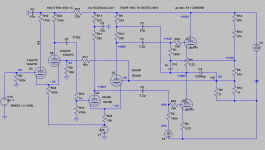
In this case is necessary a dc protection for the loudspeakers and a separated power supply for the driver section.
i happen to just read about this yesterday.. this design is a totem-pole being fed by LTP having equal-valued plate resistors, right? i read that this will intrinsically have imbalance drive to the output stage.
this is quoting from the website i read the article from:
(in totem pole,) One tube stands atop another tube, with the load attaching at the connection in between tubes; each tube must share an equal burden in driving the load; and the top tube’s cathode follows it grid, while the bottom tube’s cathode is “grounded” to either ground or a negative power supply rail. And here is where the imbalance is created, as the top and bottom tubes cannot see the same amplitude of drive voltage (as referenced to ground.) Why? Because the top tube’s cathode is following its grid, so only a fraction of the drive voltage will emerge above the cathode voltage swing; and the since the bottom tube’s cathode is grounded, its grid will see all of the drive voltage. In other words, the top tube sees effectively much less drive voltage than the bottom tube and drive voltage against transconductance equals current swing, so the bottom tube will be wildly swinging current, while the top tube lazily swings a small portion of the current. Imagine steering a bicycle with crazy handle bars: one two feet long, the other only half a foot.
what do you think? i fail to see any method of load balancing in your last circuit, is there any?
i happen to just read about this yesterday.. this design is a totem-pole being fed by LTP having equal-valued plate resistors, right? i read that this will intrinsically have imbalance drive to the output stage.
this is quoting from the website i read the article from:
what do you think? i fail to see any method of load balancing in your last circuit, is there any?
The text is correct but you have somewhat taken it out of context because it refers to a certain schematic on that site. For load balancing look carefully at the bootstrap caps from output to midpoint of the two resistors on the anode of the right driver tube. Once that is done, there has to be a similar CS connection on the left one, nove capacitor from midpoint of anode resistors on the left driver triode and ground (even better if it's not ground but minus supply of the output stage). You will find the same schematic on the tubecad site further in the text.
This is not a Totem Pole
Someone call it a S.E.P.P. but it is a Push Pull.
There are this configurations:
1) SE (very few watt)
2) SEPP or push-pull (also Futterman)
3) SRPP or Totel pole (very high output impedance not good for normal loudspeakers)
4) Circlotron (good like 2 with higher outptu impedance but more simmetric)
Last edited:
This is not a Totem Pole
Someone call it a S.E.P.P. but it is a Push Pull.
There are this configurations:
1) SE (very few watt)
2) SEPP or push-pull (also Futterman)
3) SRPP or Totel pole (very high output impedance not good for normal loudspeakers)
4) Circlotron (good like 2 with higher outptu impedance but more simmetric)
Sorry but wrong - totem-pole (name comes from the way totems are put one above the other on the totem pole) is any push-pull configuration where two same polarity devices are stacked one on top of the other (like in your amp top and bottm half of the output stage have triodes - N-tyrpe - devices). So it includes both 'SEPP' variants and SRPP (BTW good point, forgot SRPP but see nelow).
SEPP is a name that should never have been used because it just confuses the issue. In fact both futterman and inverse futterman are the same in this respect but in the first case, the devices work common cathode, in the second common anode (*). The 'SE' of SEPP has actually been 'inherited' from the fact both top and bottom half look like two SE amps one on top of the other. This is very misleading because EVERY PP amp, in terms of electrical networks are two SE amps combined.
SRPP is a push-pull topology which is only symmetric push-pull for a certain impedance, for all others it's not symmetrical (for various reasons I won't go into here). It is possible to use it for an OTL but not for the usual speaker impedances because there are really no tube that would make it practical. However, if you have, say, some Philips full-range 800 ohm speakers, you can try 🙂
(*) I.e. 'follower' - the quotes are because it's actually a really bad follwer - in an OTL the output impedance and load impedance are usually so vastly mismatched that in both CC and CP configuration with the usual tubes the gain is less than 1. However - the equations for output impedance still hold and it is vrery beneficial that it is as low as possible as 99% of speakers expect this.
Some of us crazy guys did attempt a low power (~15W) SE OTL. Pardon the language, but the schematics (there have been some minor changes to them later) are a good example.
diyaudio.com.hr • Pogledaj temu - OTL TRS 6S19P
diyaudio.com.hr • Pogledaj temu - OTL TRS 6S19P
OTL ver3 - no noise
No noise version
+330V => 2200 450V + 159ZJ 10mH 5A + 2200uF
-200V => 270uF 450V + 1K5 + 47uF 400V
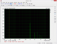
about 16W 1%
No noise version
+330V => 2200 450V + 159ZJ 10mH 5A + 2200uF
-200V => 270uF 450V + 1K5 + 47uF 400V
about 16W 1%
Attachments
Last edited:
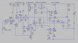
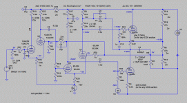
Here the last schematic for the version 3 (S.E.P.P.).
Input filter to skip RF.
You may need an input cap to limit subsonic LF because for it, the NFB does not work so it my drive input stages out of whack if they appear in the input.
Last edited:
finished first otl project
http://www.audiodesignguide.com/otl/otl2014a.html
now I will think about Corclotron
http://www.audiodesignguide.com/otl/otl2014a.html
now I will think about Corclotron
Hi,
Complementi, signore Andrea. 😎
How does it sound compared to the other OTLs you've built ?
I suppose the 6336A was chosen over the 6C33C because it's easier to drive with a ECC88 due to Miller capacitance?
Ciao, 😉
Complementi, signore Andrea. 😎
How does it sound compared to the other OTLs you've built ?
I suppose the 6336A was chosen over the 6C33C because it's easier to drive with a ECC88 due to Miller capacitance?
Ciao, 😉
I suppose the 6336A was chosen over the 6C33C because it's easier to drive with a ECC88 due to Miller capacitance?
Milller capacitance is of almost no issue as the gain of the output tubes is very low, << 1, you can drive 6C33C in OTL configuration with almost anything and get poles very high up in frequency, in my OTL's driving 6C33C with a split load phase inverter with 12BH7 or 6N6 I get poles in MHz range.
Hi,
O.K. I overlooked the output configuration...
I didn't do any measurements at all on this, it was just an impression, but when I swapped out 10 6080s for 6336As I noticed a drooping HF response and chalked it up to the driver stage not being able to drive the 6336As correctly Due to what I assumed was increased input capacitance.
In retrospect I think the tubes weren't biased correctly for the 6336As. Still not sure what caused it.
This was an eon ago BTW, didn't give it much thought back then.
Good to see you again, tubetvr. 😎
BTW, did anyone ever build a Taki OTL? With 6C33Cs?
Ciao, 😉
Last edited:
Good to see you again, tubetvr
Thank you, I haven't posted here for a long time as I am busy with my OTL business at Q-tron Audio.
The total miller capacitance of a 6C33C in OTL configuration, (it is a cathode follower) is about 50pF ((gm*Rk)/(1+Rk(1/rp+gm)))*Cgk + Cgp
The output impedance of a 12BH7 split load phase inverter with 22k anode and cathode resistors is about 250 ohm and that gives a pole of approx 12.7MHz. I use grid stoppers of 1k and then the pole goes down to approx 2.5MHz
I haven't measured it but simulations confirms that the pole is in that range.
There are many other poles in a typical OTL configuration that are several magnitudes lower but the output tube grid pole is normally of little concern for stability or frequency response
Probably is more easy to drive a 6c33c-b instead of 6336A with two section in parallel.
In this case, I did not built this amplifier from scratch, I modified an existing one with some limits and problems.
http://www.audiocostruzioni.com/a_d/elettroniche/finali-integrati/otl-6336-bebo/OTL SEPP 6336A.jpg
The amplifier now sound very good, really beyond my expectations.
Usually the main problem that remains in the OTL is the not adequate power transformer because this should not be calculated on the bias current but taking into account the series resistance of the secondary.
A 2A secondary have a primary and secondary resistances about 5ohm, this is terrible for a good bass frequency.
Also in this design I suggest 4A min to get fast and good bass frequency.
This my solution is not safety but give the idea of the final result with the right transformer.
http://www.audiodesignguide.com/my/cheap.jpg
Last edited:
A 2A secondary have a primary and secondary resistances about 5ohm, this is terrible for a good bass frequency.
5ohm sounds about correct if you also include the infleunce of the primary. The resistance in the windings influence sag at power peaks over the whole frequency range but if you use big enough capacitors bass is not affected more.
I use 10000uF for each branch and that is big enough to be able to give full output power below 10Hz with less than 1dB loss compared to midrange. This is a of course a very hard and nonrealistic case but it ensures good performance for the whole frequency range regardless of power level
I sell these components to create an OTL
Power supply components for OTL | eBay
Many persons like the sound of this OTL
OTL2014 ver 1
Soon I will test a Circlotron OTL based on this design
audiocostruzioni.com
Power supply components for OTL | eBay
Many persons like the sound of this OTL
OTL2014 ver 1
Soon I will test a Circlotron OTL based on this design
audiocostruzioni.com
I sell these components to create an OTL, caps. + transf.
Power supply components for OTL | eBay
also at less cost without Ebay
Power supply components for OTL | eBay
also at less cost without Ebay
I want to use 1 channel 4 tube 6c33c, I use electrical circuit diagrams ?????
Sorry for my bad english .
Thank !!!!
Sorry for my bad english .
Thank !!!!
- Status
- Not open for further replies.
- Home
- Amplifiers
- Tubes / Valves
- OTL 2013


