6336A OTL
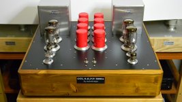
I will test this evening this configuration (see LTspice circuit) making some modification to the original project (see photo) to increase the perfomances.
This use only a pair of 6336A for each channel, a 6c33c-b on paper is a little bit better than 6336A.
I will test this evening this configuration (see LTspice circuit) making some modification to the original project (see photo) to increase the perfomances.
This use only a pair of 6336A for each channel, a 6c33c-b on paper is a little bit better than 6336A.
Attachments
Does C4 have to be that big? 4700uF to 8 ohm load will yield high pass filter of 4Hz, well below 20 Hz.
Last edited:
If I create with 12AX7 a differential stage we can add a little global feedback to obtain with only one pair of output tubes 30W at 1% thd.
Bias on the top output tube needs to be bootstrapped to the output or the grid leak R1 appears smaller due to voltage swing on it being Vgc + Vout, this increases distortion, especially at low frequency (coupling cap and apparent R1 do not have the same time constant as for the bottom half of the output stage), because the second differential stage anodes are not loaded equally.
Bias on the top output tube needs to be bootstrapped to the output or the grid leak R1 appears smaller due to voltage swing on it being Vgc + Vout, this increases distortion, especially at low frequency (coupling cap and apparent R1 do not have the same time constant as for the bottom half of the output stage), because the second differential stage anodes are not loaded equally.
Both drivers are loaded by 180K, this is necessary for the bias settting of final stage
Both drivers are loaded by 180K, this is necessary for the bias settting of final stage
They are loaded by 180k resistors, but the effective load is not 180k for both of them. The bottom 180k is a true 180k load because the AC voltage on it is the same as that on anode resistor on the anode driving it. The top 180k appears as a lower value because the voltage swing on it is higher than that on the corresponding anode resistor of the driver - which is bootstrapped to the output.
This is a common mistake in totem-pole OTL output design. The top 180k should normally be AC-connected between top output triode grid and cathode, in order to also be 'bootstrapped' to the output together with the anode resistor of the driver, hence output of the driver = voltage on the 180k resistor = Vgk of the top half of the output stage.
Instead, it is now connected between top output triode grid and AC ground (through the bias network). The AC voltage on 180k resistor becomes AC voltage on the anode resistor of the driver + output voltage, always higher than the driving voltage even though in an OTL the huge mismatch of output impedance and load makes the output voltage usually a fraction of the driving voltage (the effective Av of the output stage is <1). It is a form of Miller action. Because the 180k resistor sees a higher voltage than anode resistor of the driver, it draws more current from the driver and hence appears as a lower effective resistance to the driver - usually about 2/3 of the actual value. You can check for this easily in the simulation by removing the NFB and checking the balance of voltages on the anode resistors of the driver stage, or even simpler, the currents through the coupling caps for top and bottom half of the output stage.
In your case there will not be excessive rise of distortion for LF because the coupling caps are large (2.2u) but you can again check for the effects by lowering them to say 0.22u and checking D% at say 100Hz and 1kHz. You might be surprised by the result.
THis sort of OTL design (scaled down) can be used to drive solid state output stages in hybrid designs, where the output stage load is far lighter, and output triodes have higher mu than those typically used in a regular OTL, which makes the output stage gain much higher (>>1) and the effects I describe much more pronounced. In one design I had neary 2 orders of magnitude more distortion at LF because I failed to see the problem.
if those voltages are actual -50v and +330v the plate dissapation at 30w into 8 ohms is 100's of watts. 30w = about 2 amps peak so peak dissapation = 2 * 390/2 = 390 watts
those tubes will be destroyed at an output greater then about 2 watts
those tubes will be destroyed at an output greater then about 2 watts
stocktrader200,
The 6336A have a max dissipation of 30W for each section so 60W.
The bias should be set to have 25W on each seaction so 25W / (320V / 2) = 0.15A.
The peak until 350W for 2 sections will be supported by the tubes without problems, all tubes used in OTL work in this condition.
The 6336A have a max dissipation of 30W for each section so 60W.
The bias should be set to have 25W on each seaction so 25W / (320V / 2) = 0.15A.
The peak until 350W for 2 sections will be supported by the tubes without problems, all tubes used in OTL work in this condition.
Attachments
The new driver section has been tested this evening and work without problems.
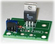
I have use the Kand Audio modules (not cascode with medium heatsink) to implement this current generator (12$ each).
I have use the Kand Audio modules (not cascode with medium heatsink) to implement this current generator (12$ each).
Attachments
Last edited:
ilimzn ,
Are you speaking about Vgk variation during signal ?
Yes. In your case Rg is 180k so on the top side appears to be about ~120k, in parallel with 20k on the driver (If I read it correctly, tiny letters) on the top it's 17.14k, on the bottom 18k load. Hence slight asymetry. Easy to solve by connecting the bias filter cap C10 for the top half to the output instead of ground.
In your case it's not a big error, because the 180k resistors are >>20k in the driver anodes, but does produce a bit of DC as output power goes up due to asymmetry (asymmetry gets even order harmonics, but keep in mind DC = harmonic 0 is also even, so asymmetry generates a DC offset dependent on output level). If different tubes are used for the output, such as 6S33S which require Rg<=100k, the asymmetry gets worse.
Top tube
anode = +330V
cathode = +160V
so grid must be at 160V - 50V = +110V
Bottom tube
anode = 160V
cathode = 0V
so grid must be at 0V - 50V = -50V
if you mean connect C10 to loudspeaker output ? yes, this give a better simmetric bias setting.
Attachments
Last edited:
if you mean connect C10 to loudspeaker output ? yes, this give a better simmetric bias setting.
Yes, but better before the output cap, to anode of bottom tube. This way both 180k grid leaks for top and bottom output tube appear exactly the same to the driver and there is no asymmetry.
R6 bottom end can remain connected to GND like before, so it does not pull the output towards +B of output stage while tubes are not heated up yet.
Also, you have a cap from the top of the 20k anode resistor of the left side of the driver stage to ground. For a little more ripple rejection, it can go to -B of the output stage instead of GND.
I cannot connet 47K before output cap. because this point is at +165V and not at 0V
Attachments
First measurements
This evening using 6336A
19W with 1.7% not bad for only 2 tubes
I should try soon also 6c33c-b instead of 6336A
This evening using 6336A
19W with 1.7% not bad for only 2 tubes
I should try soon also 6c33c-b instead of 6336A
Attachments
Last edited:
I cannot connet 47K before output cap. because this point is at +165V and not at 0V
No no, C10 before the output cap in the old schematic, now C4, as you have drawn. Disregard what I said about 47k, did not notice a change in the schematic.
Would be good to make C4 about as big as coupling cap or larger (test for distortion at 50Hz).
Last edited:
- Status
- Not open for further replies.
- Home
- Amplifiers
- Tubes / Valves
- OTL 2013