resistor helps to equalise the current sharing between the two valves
Yes they are necessary when paralleling valves but need to be much larger to be effective, they have often been omitted in commercial OTLs with disastrous results. In the datasheet of 6C33C it is recommended to derate max current for each tube when used in parallel even when current sharing resistors are used.
Yes they are necessary when paralleling valves but need to be much larger to be effective....
Agreed. At a guess 1 - 2 ohms would be useful, but even then only with matched tubes with individual bias settings. My own 6C33C project is still in boxes and on paper - too much real life stuff getting in the way.
This is not bad, which model have you used ?
From Dmitry's website linked above.
** 6C33CCRV ************************************************************
* Created on Wed Oct 12 16:43:48 PDT 2005 using tube.model.finder.PaintKIT
* URL: http://www.mclink.it/com/audiomatica/tubes/6c33c.htm
*--------------------------------------------------
.SUBCKT TRIODE_6C33CCRV 1 2 3 ; P G K ;
+ PARAMS: CCG=3P CGP=1.4P CCP=1.9P RGI=2000
+ MU=2.7090 EX=1.4629 KG1=406.875 KP=14.8125 KVB=11.4375 VCT=0.8320 ; Vp_MAX=400.0 Ip_MAX=0.6 Vg_step=30.0
*--------------------------------------------------
E1 7 0 VALUE={V(1,3)/KP*LOG(1+EXP(KP*(1/MU+(VCT+V(2,3))/SQRT(KVB+V(1,3)*V(1,3)))))}
RE1 7 0 1G
G1 1 3 VALUE={(PWR(V(7),EX)+PWRS(V(7),EX))/KG1}
RCP 1 3 1G ; TO AVOID FLOATING NODES
C1 2 3 {CCG} ; CATHODE-GRID
C2 2 1 {CGP} ; GRID=PLATE
C3 1 3 {CCP} ; CATHODE-PLATE
D3 5 3 DX ; FOR GRID CURRENT
R1 2 5 {RGI} ; FOR GRID CURRENT
.MODEL DX D(IS=1N RS=1 CJO=10PF TT=1N)
.ENDS
No not exactly, there is an additional term (VE in the formula C in the model) to introduce the kink see formula (3) in here http://www.excem.fr/download/usergui5.pdf
The problem is that the kink is not so smooth as predicted in reality the curves bends quite abrupt at a specific low current, you can see it best at around -100V grid voltage, what is needed is either a polynom with much higher order or a piecewise linear approximation for small steps of current.
Got it, Equation (3) replaces (1) for the 6C33C. What do you make of the Audiomatic curves? There is hardly any kink in any of the curves, which were taken from the Sofia curve tracer.
What do you make of the Audiomatic curves? There is hardly any kink in any of the curves, which were taken from the Sofia curve tracer.
If you look at the curves in post 52 you can see clearly see the kink at the curve for -90V grid voltage, (also for other grid voltages). You can also see that the model doesn't follow the curves for low currents. The curves still look smoother than what I have measured but it can be due to low resolution.
I have never used LTSpice is it based on PSpice? I use something called Superspice that is a version based on Spice 3 and then it works.
Can you help me to convert this model to LTSpice ?
If you look at the curves in post 52 you can see clearly see the kink at the curve for -90V grid voltage, (also for other grid voltages). You can also see that the model doesn't follow the curves for low currents. The curves still look smoother than what I have measured but it can be due to low resolution.
Now I see it... So the kinks vary from tube to tube and is dependent on the resolution of the curve tracer/measuring device. Hard to design that way, so as audiodesign suggested, we can merely use the simulations for general direction, and the final circuit still needs to be tweaked in situ, provided that the SPICE models we use have relatively good correlations with the TUTs.
Can you help me to convert this model to LTSpice ?
Here is the code I came up with, please see if it works in LTSpice...
.SUBCKT 6C33C_Excem 1 2 3
+ PARAMS: G=5.126m MU=2 B=18.79 C=0.944 Vc=0.22 ALPHA=1m BETA=5U RGI=2000
B1 1 3 I={G}*(1+(V(2,3)/({B}-(V(2,3)/{C}))))*(V(2,3)+((V(1,3)+{Vc})/{MU}))**1.5
RE1 1 3 1G
B4 6 0 V=IF( V(2,3)>0 ,{ALPHA}*V(2,3)**1.5 , {BETA}/-(V(2,3)-.1) )
RE2 6 0 1G
B5 2 3 I=V(6,0)
RE3 2 3 1G
C1 2 3 20P
C2 2 1 10P
C3 1 3 7P
.ENDS
Still looks far from usable...
6C33C_Excem vs. datasheet:
An externally hosted image should be here but it was not working when we last tested it.
Both these 2 models work on LTSpice
** 6C33CCRV ************************************************** **********
* Created on Wed Oct 12 16:43:48 PDT 2005 using tube.model.finder.PaintKIT
* URL: http://www.mclink.it/com/audiomatica/tubes/6c33c.htm
*--------------------------------------------------
.SUBCKT TRIODE_6C33CCRV 1 2 3 ; P G K ;
+ PARAMS: CCG=3P CGP=1.4P CCP=1.9P RGI=2000
+ MU=2.7090 EX=1.4629 KG1=406.875 KP=14.8125 KVB=11.4375 VCT=0.8320 ; Vp_MAX=400.0 Ip_MAX=0.6 Vg_step=30.0
*--------------------------------------------------
E1 7 0 VALUE={V(1,3)/KP*LOG(1+EXP(KP*(1/MU+(VCT+V(2,3))/SQRT(KVB+V(1,3)*V(1,3)))))}
RE1 7 0 1G
G1 1 3 VALUE={(PWR(V(7),EX)+PWRS(V(7),EX))/KG1}
RCP 1 3 1G ; TO AVOID FLOATING NODES
C1 2 3 {CCG} ; CATHODE-GRID
C2 2 1 {CGP} ; GRID=PLATE
C3 1 3 {CCP} ; CATHODE-PLATE
D3 5 3 DX ; FOR GRID CURRENT
R1 2 5 {RGI} ; FOR GRID CURRENT
.MODEL DX D(IS=1N RS=1 CJO=10PF TT=1N)
.ENDS
.SUBCKT 6C33C_Excem 1 2 3
+ PARAMS: G=5.126m MU=2 B=18.79 C=0.944 Vc=0.22 ALPHA=1m BETA=5U RGI=2000
B1 1 3 I={G}*(1+(V(2,3)/({B}-(V(2,3)/{C}))))*(V(2,3)+((V(1,3)+{Vc})/{MU}))**1.5
RE1 1 3 1G
B4 6 0 V=IF( V(2,3)>0 ,{ALPHA}*V(2,3)**1.5 , {BETA}/-(V(2,3)-.1) )
RE2 6 0 1G
B5 2 3 I=V(6,0)
RE3 2 3 1G
C1 2 3 20P
C2 2 1 10P
C3 1 3 7P
.ENDS
and this does not work, from lamp.lib
.SUBCKT V6C33C-B 1 2 3
* A G C
*
* X1 1 2 3 TRIO3 {G=5.126m MU=2 B=18.79 C=.944 Vc=.22}
* X2 2 3 Igrid {ALPHA=1m BETA=5U}
X1 1 2 3 TRIO3
X2 2 3 Igrid
C1 1 2 10PF
C2 2 3 20PF
C3 1 3 7PF
.ENDS
.SUBCKT Igrid G1 C
+ PARAMS: ALPHA=1m BETA=5U
B4 6 0 V=V(G1,C)>0 ?{ALPHA}*V(G1,C)^1.5 : {BETA}/-(V(G1,C)-.1)
B5 G1 C I=V(6,0)
.ENDS
.SUBCKT TRIO3 A G C
+ PARAMS: G=5.126m MU=2 B=18.79 C=.944 Vc=.22
B1 A C I={G}*(1+(V(G,C)/({B}-(V(G,C)/{C}))))*(V(G,C)+((V(A,C)+{Vc})/{MU}))^1.5
.ENDS
Last edited:
Hybrid ver1a - part 2
Today I would like to give more infomations about this circuit which seems simple but contains some particularities.
The first stage is a differential cascode configuration, the jfet add an extra voltage gain to the tube to obtain a good open loop gain necessary to be drive the amplifier with 1Vrms.
We can study different solutions for the cascode to eliminate the jfet.
The current mirror transfers the current from the first stage to the second without altering the signal.
The two controlled current generators drive the output tube with identical signals even if with different reference ground.
The current mirror has been configurated to amplify the current (from 1.5mA to 15mA) but this process does not affect the signal because if I use all Re = 1Kohm and 22 x mosfet all work in the same condition.
You can use P type Mosfet or PNP transsitor, the FQP3P50 and FQP4P40 by Fairchild should be good (TO220 500V 85W).
I don't find a good PNP with 500V, please help me.
In the simulations a single device in the second stage give better performances.
Attachments
Last edited:
Full vacuum tubes DC coupled - first test
This is the first test on a DC coupled design with only vacuum tubes.
The circuit should be controlled in the next days, there are many factors to check before build it.
The output tubes must be disconnected from power supply in the switch-on phase.
This is the first test on a DC coupled design with only vacuum tubes.
The circuit should be controlled in the next days, there are many factors to check before build it.
The output tubes must be disconnected from power supply in the switch-on phase.
Attachments
Last edited:
Frst conclusion
After all this series of simulations I have not found an elegant solution with high-performance for this type of circuit.
The hybrid solutions do not make sense to me because if the amplifier is hybrid we accept mosfets and transistors on the signal path, then the final stage should be solid state.
The Futterman and the Technics are very asymmetric circuits that work but do not guarantee a perfect functioning of the output tubes.
Surely the high factor of feedback, 19dB min with 4 6C33C-B tubes per channel, cancel many flaws but ...
At this point I'm seriously thinking of going back to Circlotron, so use the actual transformers for the initials tests and after rebuild a pair to create monoblock (the best is separate the anodic to filaments so 4 transfomers).
Last edited:
Output tubes - first data
Here some data about the output tubes to use in OTL.
Of course the aim is to find the tubes for a low output impedance and high current.
Here some data about the output tubes to use in OTL.
Of course the aim is to find the tubes for a low output impedance and high current.
Attachments
Last edited:
OTL Circlotron - first 3 circuits
Here the first 3 solutions to create an OTL Circlotron:
1) test6a - feedback 15dB - 50W with 1.6Vrms and 1.0% thd
only two stages and a single driver power supply but very low voltage gain
2) test7a - feedback 15dB - 50W with 0.7Vrms and 0.9% thd
3) test8a - feedback 15dB - 50W with 0.7Vrms and 0.7% thd
one more capacitor on the signal path
It is possbile use the 12BH7 tubes instead of 12AU7.
Attachments
I want to try a configuration more or less similar to yours, but in a different way. My idea is to mix an Augmented Cathode Follower (Search in internet for it) plus a WCF as final stage, and with a gain of 10 or 15 times, to drive a 600 ohm headphone. Also split power supply. Output tubes are around a pair of 6S4, a pair of 6DE7 or 12W4. I have some of all them to try.
Hi Audiodesign !
Why you not try with 4 DC coupled CF triode driver , where each output 6c33c grid have associated separate DC coupled driver and in the same time separate bias pot, all that supplied from bipolar PSU .
With 4 DC coupled drivers you can easy avoid blocking distortion generated from 6c33c grid coupling caps , and in same time that solution is electricaly and sonicaly beneficial in many different ways to .
For example that`s the way how Atma-Sphere Novacron is done ,
later your input voltage gain stage can be designed and done in many different ways , depending only from question from what you prefer for .
Regards !
I have exchanged with a my friend some parts with a 1500VA transformer for OTL and 8 x RIFA 3300uF 200V capacitors.
The my old experience is described in this webpage:
Andrea Ciuffoli - Home Page
It is too simple create a new VARIATION ON THE FUTTERMAN so I would like to get new ideas about this project.
My experience in amp building told a story of
Disappointing pro experiment.
tubes are best used in common cathode configuration.no pro design can utilize that. So sound quality suffered. After all, transform is the way to go for impedence match from tube plate output to speakers.
another configuration
Here another configuration based on following design:
Transcendent Audio (United States Patent: 5604461)
http://www.diyaudio.com/forums/tubes-valves/178353-otl-designed-glen-orr-audioxpress-3.html#29
Audiocostruzioni - Il Portale dell'alta fedelt amatoriale
Audiocostruzioni - Il Portale dell'alta fedelt amatoriale
The purpose is always to drive the final valves with two drivers with equal reference mass to configure both final valvoles as cathode follower.
If we compare this circuit with the Futterman here the advantage is to have a driver that amplifies but the disadvantage is the necessity to require a large value capacitor on the signal (see C7 = 47uF).
here two versions, with a single power supply and with a dual power supply.
Attachments
Last edited:
Interesting all those different possebilities 😎
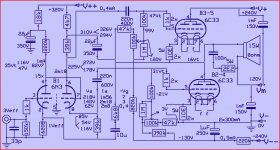
Let's play along,a sort of inverted Futterman.
Some positive feedback for a geater open loop gain and a bit of negaive feedback to calm things down 😀
There are suposed to be four 6C33 but the drawing shows but two ,makes it more open.
It's only a wild idea,after someone asked "what is there to do with Russian tubes"
Mona
Attachments
- Status
- Not open for further replies.
- Home
- Amplifiers
- Tubes / Valves
- OTL 2013