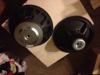
Is that a Dayton on the right?
That magnet looks so small and weird. Good to see the packaging on the Faitals was triple boxed. So let the building begin. 😀
That magnet looks so small and weird. Good to see the packaging on the Faitals was triple boxed. So let the building begin. 😀
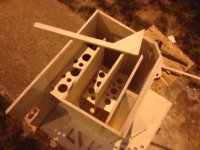
Is all material 3/4" or is the baffle 1"?
I only ask because I couldnt tell from the dado. Also I have been wanting to someday use a 1" thick baffle like DSL and was hoping your doing something similar. Anyways back to the build.
I only ask because I couldnt tell from the dado. Also I have been wanting to someday use a 1" thick baffle like DSL and was hoping your doing something similar. Anyways back to the build.
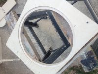
made a little more progress today before tornado warnings drove me inside...
was slowed down quite a bit by the 2 hour worthless phone call with Parts express.
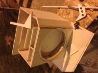
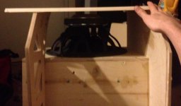
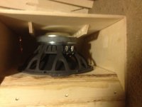
I didn't notice it before, but the mouth section looks a little "tight". How much of it is going to be shaded by the driver's bulk?
eh, its pretty shady in there certainly.
not any more than the tham 15 though (even less actually)
I may go ahead and recess another 1/4 inch.... i've got about 1.2 inches between the vent and the back panel as of right now.
not any more than the tham 15 though (even less actually)
I may go ahead and recess another 1/4 inch.... i've got about 1.2 inches between the vent and the back panel as of right now.
Attachments
Last edited:
eh, its pretty shady in there certainly.
not any more than the tham 15 though (even less actually)
I've been trying to figure out a way to incorporate the effect of the shading on the cross-section in that area. I don't think HornResp can model the effect of driver shading the mouth, at least not directly. I'm going to guess that the Fb and upper bass response is reduced, the amount depending on how much of the mouth section is shaded.
Once I come up with an equation to calculate the driver's cross-sectional area at different points (I'm going to model it as a truncated cone capped by a flattish cylinder (representing the magnet structure), I'm going to incorporate it into my TH layout spreadsheet, so I can have a better visual representation of the impact.
I expect that excursion will be slightly increased, and upper bass shall be diminished as well (with an increase in the 140 dip too). thankfully, there's plenty of excursion to spare up there...
guess we wont know till I finish (and verify I even have the right driver) and I run some measurements :/
EDIT
so, the volume of the area where the driver is, is 39 liters. the driver occupies 5.1 liters of this space, a 12 percent reduction in volume. dunno what this translates too, again.
guess we wont know till I finish (and verify I even have the right driver) and I run some measurements :/
EDIT
so, the volume of the area where the driver is, is 39 liters. the driver occupies 5.1 liters of this space, a 12 percent reduction in volume. dunno what this translates too, again.
Last edited:
Once I come up with an equation to calculate the driver's cross-sectional area at different points (I'm going to model it as a truncated cone capped by a flattish cylinder (representing the magnet structure), I'm going to incorporate it into my TH layout spreadsheet, so I can have a better visual representation of the impact.
CAD + excel version...

That looks like its a representation of the cone correction to be applied at S2, not the impact of the driver's cone, basket and magnet structure at S3 (or S4, if you're modelling the TH in HornResp using four segments)
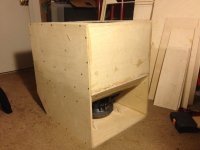
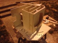
box 1 is just about buttoned up. just need to do the back reflector piece, and secure the speakon jack plate. 😀
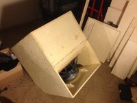
Oh yeah, that driver's bulk seems to be noticeably reducing the cross-sectional area of the horn at that point...
that picture was just for you brian lol
like I said, its about the same reduction (or less) than the THAM15 which is generally well regarded here.
like I said, its about the same reduction (or less) than the THAM15 which is generally well regarded here.
That looks like its a representation of the cone correction to be applied at S2, not the impact of the driver's cone, basket and magnet structure at S3 (or S4, if you're modelling the TH in HornResp using four segments)
You can get the restriction of the frame and motor modeled in Akabak or ABEC3. I include this in my final drafts but truthfully it really doesn't make as much of a difference as you would think. It is noticeable with overlays but isn't really enough to spend a lot of time on IMO.
good to hear it josh.
Mannnn really wish that PE had the DATS in stock.
anyone have a pic of the rig they use with REW to measure impedance? I have both an audio 8 dj, and a presonus firebox 2i2o available to use...
Mannnn really wish that PE had the DATS in stock.
anyone have a pic of the rig they use with REW to measure impedance? I have both an audio 8 dj, and a presonus firebox 2i2o available to use...
anyone have a pic of the rig they use with REW to measure impedance?
Check this out:
Lilmike’s DIY Impedance Measurement Jig
- Home
- Loudspeakers
- Subwoofers
- OTH40C 15" loaded Compact TH Flat to 40hz