One more question!😉
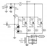
In the attached Pathos TT output section's schem:
I know it use also a 120mH/1Rdc choke and the source voltage is on the inductor 3,25V (=3,25A).
How much is the gate voltage with the paralleled Fets? Need I calculate with 3*4V Vgs?
I think it is a good way to spread the heat between the Fets.
But than it is not an OTA amp anymore....
Greets:
Tyimo😀
Attachments
The bias voltage remains the same no matter how many mosfets you put in //.
Using two mosfets instead of one might be a good idea, but more than two shouldn´t be necessary.
The mosfets might need to be matched, I used 5 x IRF540 in // once and one of them handled almost all the current even with 0,33R source resistors.
Use as few as you can get away with.
Using two mosfets instead of one might be a good idea, but more than two shouldn´t be necessary.
The mosfets might need to be matched, I used 5 x IRF540 in // once and one of them handled almost all the current even with 0,33R source resistors.
Use as few as you can get away with.
Don't do it like that.
O.K. Mads! I wanted anyway to build the schematic with your style, to stay as close as possible to the original OTA amp. 😉
I would like only learn and understand how amps and different arrangements are working.
Tyimo
The bias voltage remains the same no matter how many mosfets you put in
Thanks! So in this case (Pathos TT) I need to make 7.25V Gate voltage with the voltage divider?
I calculated 15-19V with the known resistor values.....?

Tyimo
Mads!
Need I put a resistor before/between the inputcap and ground?
In the SEWA and OTA3.5 you did, but in the OTA7 not.
What value is the best?
Tyimo
Need I put a resistor before/between the inputcap and ground?
In the SEWA and OTA3.5 you did, but in the OTA7 not.
What value is the best?
Tyimo
Tyimo said:
O.K. Mads! I wanted anyway to build the schematic with your style, to stay as close as possible to the original OTA amp. 😉
I would like only learn and understand how amps and different arrangements are working.
Tyimo
In that case, the input Z is the paralelled value of the impedances from gate to + and gate to gnd. 510K+100K//210K=156K but is varying with pot setting. Also, the psu ripple is injected directly into the signal

Tyimo said:Mads!
Need I put a resistor before/between the inputcap and ground?
In the SEWA and OTA3.5 you did, but in the OTA7 not.
What value is the best?
What value need for the resistore befor the input cap to the ground?
Tyimo
It's only a bleeder resistor to discharge the input cap when the amp is turned off. This to prevent pops when you plug in signal cables. It is good practice to use it, but it is really superflous in a power amp. You should not plug in anything while the amp is on. Same thing with the output res. to gnd. It also changes the input Z ; In Z is the paralelled value of this resistor and the the res. from bias divider to gate.
Input cap low frequency rollof:
F=1/(2*pi*RC) Hz
for example 1uF and 100K=1/(2*3,14*100e3*1e-6)=1,6Hz
Same with output rolloff.
😉
In that case, the input Z is the paralelled value of the impedances from gate to + and gate to gnd. 510K+100K//210K=156K but is varying with pot setting. Also, the psu ripple is injected directly into the signal
Thanks Mads! I understand!!

Back to your arrangement:
What is better for the voltage divider to use higher or lower resistore values? I mean from 24V to make 7V and if the input imp. resistore is independent from the voltage divider parts??
R1=510K R2=210K
or
R1=29K R2=12K ?
or even go down into the simple Ohm region?
Tyimo
Thanks Mads for the input cap and resistore calulations!
This online writing getting faster and faster! I can't keep pace with you!😀
I have to get out because the dinner is waiting for me.
Thanks for the helps!!!!
Tyimo
This online writing getting faster and faster! I can't keep pace with you!😀
I have to get out because the dinner is waiting for me.
Thanks for the helps!!!!
Tyimo
Tyimo said:
Thanks Mads! I understand!!
Back to your arrangement:
What is better for the voltage divider to use higher or lower resistore values? I mean from 24V to make 7V and if the input imp. resistore is independent from the voltage divider parts??
R1=510K R2=210K
or
R1=29K R2=12K ?
or even go down into the simple Ohm region?
Tyimo
Use divider values in the 10K-100K range 😉
Good morning Mads!😀
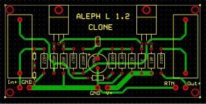
Nice schematic! What do you think is it works?😀
I think I will try to build.
Thanks!!!
Greets:
Tyimo
Nice schematic! What do you think is it works?😀
I think I will try to build.
Thanks!!!
Greets:
Tyimo
Is your PCB designed for standard parts or for SMD?
If it is with normal parts I coud test it for you and for me!😀
Tyimo
If it is with normal parts I coud test it for you and for me!😀
Tyimo
It is a mixed mixed technology board. How about if I mounted the SMT parts and you mounted the PTH parts and tested it? Do you have a oscilliscope and signal generator?
Do you have a oscilliscope and signal generator?
I havn't got, but my friend has! So, I could test it...
- Status
- Not open for further replies.
- Home
- Amplifiers
- Pass Labs
- OTA - One Transistor Amplifier