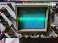
If you are meaning the trace centered, yes. I always center it before testing anything. Before I did that test I noticed the trace had dropped way down on the screen. Had to turn the adjustment knob past where is normal to center it.
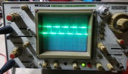
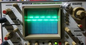
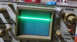
So, I gave it a couple more adjustments (swift kicks, LOL) and got the trace back centered as it usually does. Here are the new photos...second photo is of pin 9. Third photo is of pin 10.
Scope set at 2v/div and 20us
The DC voltage of pin 8 and 11 of the 494 are:
pin 8. +5.51v
pin 11. +5.53v
So, I gave it a couple more adjustments (swift kicks, LOL) and got the trace back centered as it usually does. Here are the new photos...second photo is of pin 9. Third photo is of pin 10.
Scope set at 2v/div and 20us
The DC voltage of pin 8 and 11 of the 494 are:
pin 8. +5.51v
pin 11. +5.53v
Attachments
As I mentioned before with the amp being powered through the resistor ("choke") something is pulling the voltage down. The DC voltage at the amp power terminal should be +12.3v but it is +7.8v. This is obviously effecting the voltages though out the rest of the amp.
Last edited:
What value resistor are you using for a limiter? Do you have another one that you could connect in parallel?
The last scope image shows the waveform not going back to ground. Check the base terminal of all of the driver pairs. Is there one pair that has their base not going back to near ground?
The last scope image shows the waveform not going back to ground. Check the base terminal of all of the driver pairs. Is there one pair that has their base not going back to near ground?
For a limiter I'm using three 50w 6ohms resistors in parallel. I don't have another resistor on hand.
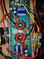
I found the pair of drivers that doesn't have their base going back to ground, (see attached photo of board circled in yellow, wave form is second photo).
The pair of drivers just below them (circled in red) isn't producing a wave form at all (third photo). Those are the drivers for the set of FET's in post #49 that has the distorted waveform. I tried pulling one of my limiter resistors out of circuit to see if it made a difference and had no effect on the waveform, that is lack of it.
Attachments

Last edited:
For the drivers producing no drive, is the A56 collector going to ground via the 10 ohm resistor and the collector of the A06 being fed 12v?
Have you checked them?
Confirm that you read about 100 ohms from leg 1-3 of all of the FETs in that bank. If so, will the amp power up without pulling excess current with those two drivers removed? Connect through your limiter and have the FETs clamped.
Have you checked them?
Confirm that you read about 100 ohms from leg 1-3 of all of the FETs in that bank. If so, will the amp power up without pulling excess current with those two drivers removed? Connect through your limiter and have the FETs clamped.
For the drivers producing no drive, the A56 collector is going to ground via the 10 ohm resistor. The collector of the A06 is being fed +5.03v DC the same as the other side...again do to the low voltage at the amp power connection.
I pulled the A56 and A06 both checked within tolerance.
I noted voltage differences at the bases of the A06 drivers, see attached photo
I pulled the A56 and A06 both checked within tolerance.
I noted voltage differences at the bases of the A06 drivers, see attached photo
Attachments
I did a complete check on them. When you mentioned open junction it got me thinking so checked. Turns out that the cold FET A06 driver wasn't a A06 it was a A56. Apparently there was a A56 mixed in with my A06's.
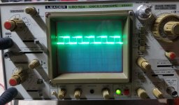
With a A06 now installed the wave forms are the same on the bases of all the drivers. Also the same on pins 9 and 10 of the 494. Voltage on pins 9 and 10 is the same.
FET's getting hot has now shifted to the upper sets both sides.
With a A06 now installed the wave forms are the same on the bases of all the drivers. Also the same on pins 9 and 10 of the 494. Voltage on pins 9 and 10 is the same.
FET's getting hot has now shifted to the upper sets both sides.
Given that the DC voltage is still at +7.8v at the amp power terminal, I suspect the idle current draw is still higher than it should be. I don't have another fuse for my meter at the moment to test for sure.
Not sure I understand your second question, "outputs for the supply"?
Not sure I understand your second question, "outputs for the supply"?
Do you think you could have installed a capacitor backwards?
Measuring the voltage across any resistor will allow you to calculate current but the current here is too high to use the voltage across 2 ohms to be useful. It's easy to calculate the current across a value like 1 ohm or 0.1 ohms.
Measuring the voltage across any resistor will allow you to calculate current but the current here is too high to use the voltage across 2 ohms to be useful. It's easy to calculate the current across a value like 1 ohm or 0.1 ohms.
- Status
- This old topic is closed. If you want to reopen this topic, contact a moderator using the "Report Post" button.
- Home
- General Interest
- Car Audio
- Orion HCCA 2100 no rail voltage.